
Building material crushing mixing and feeding device

A technology for buildings and silos, which is applied in the field of feeding machines, can solve the problems of unavoidable smoke and dust, increase the completion time of construction projects, and inconvenient use of building materials, so as to facilitate the closed crushing work, shorten the completion time, and avoid gas leakage. The effect of venting

Inactive Publication Date: 2019-01-01
GUIZHOU UNIV
View PDF7 Cites 2 Cited by
  • Summary
  • Abstract
  • Description
  • Claims
  • Application Information

AI Technical Summary

Problems solved by technology

[0003] A Chinese patent discloses a mixing and feeding device for colored brick pigments. (Authorized Notification No. CN104118059A). This patented technology uses multiple hoppers to store colored brick pigments of different colors, which can avoid the pollution of colored brick pigments and improve the quality of colored bricks. The quality is high, and the screw conveyor is used for feeding, which has the advantages of safe and convenient operation and low manufacturing cost. At the same time, the feeding rate is easy to control, which is conducive to improving the weighing accuracy. However, the existing building material crushing and lifting devices are not equipped with electric telescopic rods and The cover plate is inconvenient to close the crushing upper hopper when crushing materials, and it is not convenient for the crushing work of building materials. There is no clean room, and it is not convenient to absorb, filter and purify the smoke generated in the crushing upper hopper. Avoid the user from inhaling too much smoke and dust, which will endanger the health of the user. There is no transmission mechanism, and the mixed building materials in the mixing room cannot be transported, which is not convenient for the use of building materials, which will increase the time for the completion of the construction project.

Method used


Image

  • Building material crushing mixing and feeding device
  • Building material crushing mixing and feeding device
  • Building material crushing mixing and feeding device

Examples


Embodiment Construction

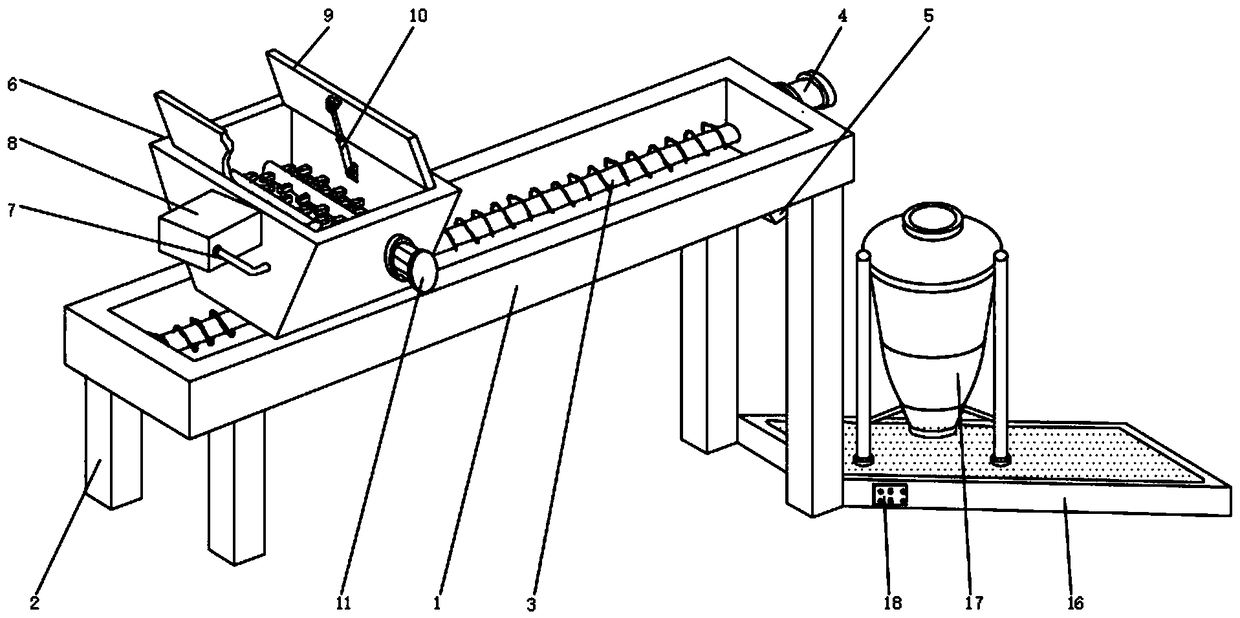
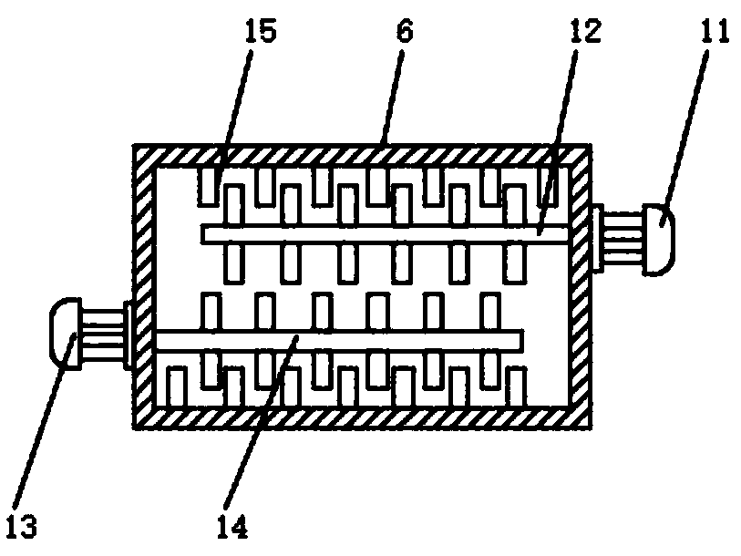
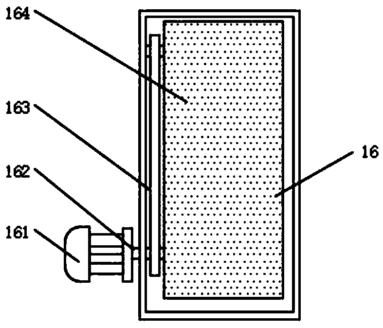
[0022] see Figure 1~4 , in an embodiment of the present invention, a building material crushing and mixing feeding device includes a feeding channel 1, a stepping motor 4 is fixedly installed on the side surface of the feeding channel 1, and a helical twister is installed on the inner rotation of the feeding channel 1 Dragon 3, the bottom end of the feeding channel 1 is fixedly installed with a support column 2, and the bottom end of the material delivery channel 1 is provided with a discharge port 5 near the rear side of the supporting column 2, and the inside of the feeding channel 1 corresponds to the spiral twisting The upper end of the dragon 3 is connected with a crushing upper material bin 6, and the upper end of the crushing upper material bin 6 is rotatably connected with a cover plate 9, and a first motor 11 is fixedly installed on the front surface of the crushing upper material bin 6, and the crushing upper material bin 6 A first crushing tooth 12 is installed at ...


PUM


Abstract

The invention discloses a building material crushing mixing and feeding device, which comprises a material conveying passage, wherein a step motor is fixedly arranged on the side surface of the material conveying passage; a spiral auger is rotationally arranged inside the material conveying passage; the bottom end of the material conveying passage is fixedly provided with a support post; a discharging opening is formed in a position, near the back side of the support post, of the bottom end of the material conveying passage; a crushing feeding cabin is connected in a position, corresponding tothe upper end of the spiral auger, inside the material conveying passage. An electric telescopic rod and a cover plate are installed, so that the cabin sealing treatment can be conveniently performedon the crushing feeding cabin during the material crushing; the occurrence of outward seepage of the gas in the crushing feeding cabin is avoided; a purification chamber is installed; smoke dust generated in the crushing feeding cabin can be conveniently adsorbed and filtered to reach the goal of purification treatment; the dust flying in the construction site is reduced; a transmission mechanismis installed, so that the mixed building material in the mixing chamber can be conveyed; the building material in the building chamber can be conveniently used.

Description

technical field [0001] The invention relates to the technical field of feeding machines, in particular to a crushing and mixing feeding device for building materials. Background technique [0002] In the construction of construction projects, it is often necessary to crush building materials, and transport the broken building materials to the mixing chamber, and convey different building materials to the mixing chamber. The mixer uses mechanical force and gravity to combine two or Mechanical equipment that mixes two or more materials uniformly can also increase the contact surface area of ​​materials during the mixing process to promote chemical reactions and accelerate physical changes. [0003] A Chinese patent discloses a mixing and feeding device for colored brick pigments. (Authorized Notification No. CN104118059A). This patented technology uses multiple hoppers to store colored brick pigments of different colors, which can avoid the pollution of colored brick pigments ...

Claims


Application Information

Patent Timeline
Patent Type & Authority Applications(China)
IPC IPC(8): B01F3/20B01F15/00B01F15/02B01D50/00B01F23/70
CPCB01D50/00B01F23/71B01F35/184B01F35/7541
Inventor 张玉涛杜斌车小林沈明轩郭仔翔
Owner GUIZHOU UNIV
Learn More