Road bridge width limiting device

A bridge and width technology, which is applied in the field of road and bridge width limiting devices, can solve the problems of inability to conveniently and quickly disassemble, limit the height of vehicles, and cannot adjust the width at any time according to needs.

Active Publication Date: 2019-01-01
绍兴市卓诚新材料有限公司
View PDF6 Cites 7 Cited by
  • Summary
  • Abstract
  • Description
  • Claims
  • Application Information

AI Technical Summary

Problems solved by technology

[0005] In order to solve the above-mentioned technical problems, the present invention provides a device for limiting the width of roads and bridges to solve the problem that the existing devices for limiting the width of roads and bridges are mostly fixed-sized width-limiting doors with simple structure and poor functionality. The width of th...

Method used


Image

  • Road bridge width limiting device
  • Road bridge width limiting device
  • Road bridge width limiting device

Examples


Embodiment

[0031] as attached figure 1 to attach Figure 8 Shown:

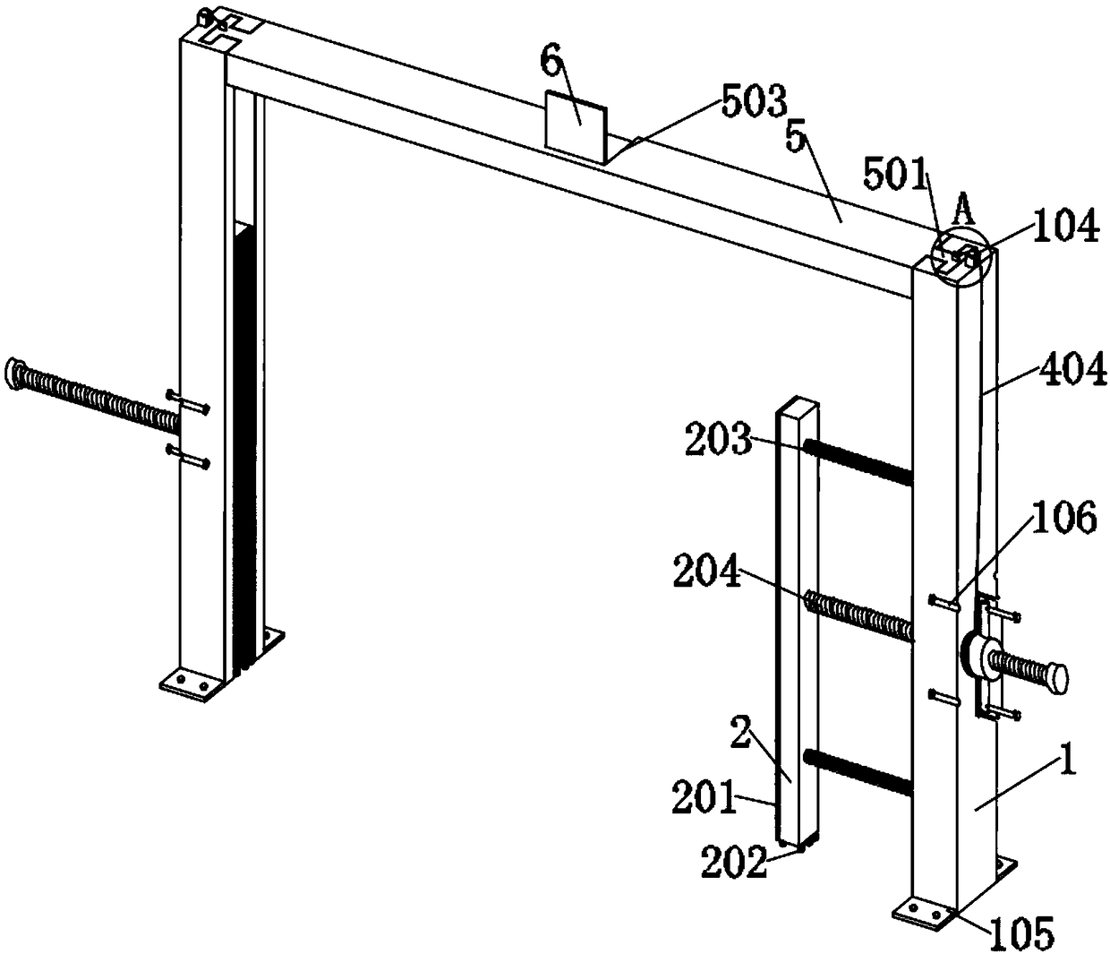
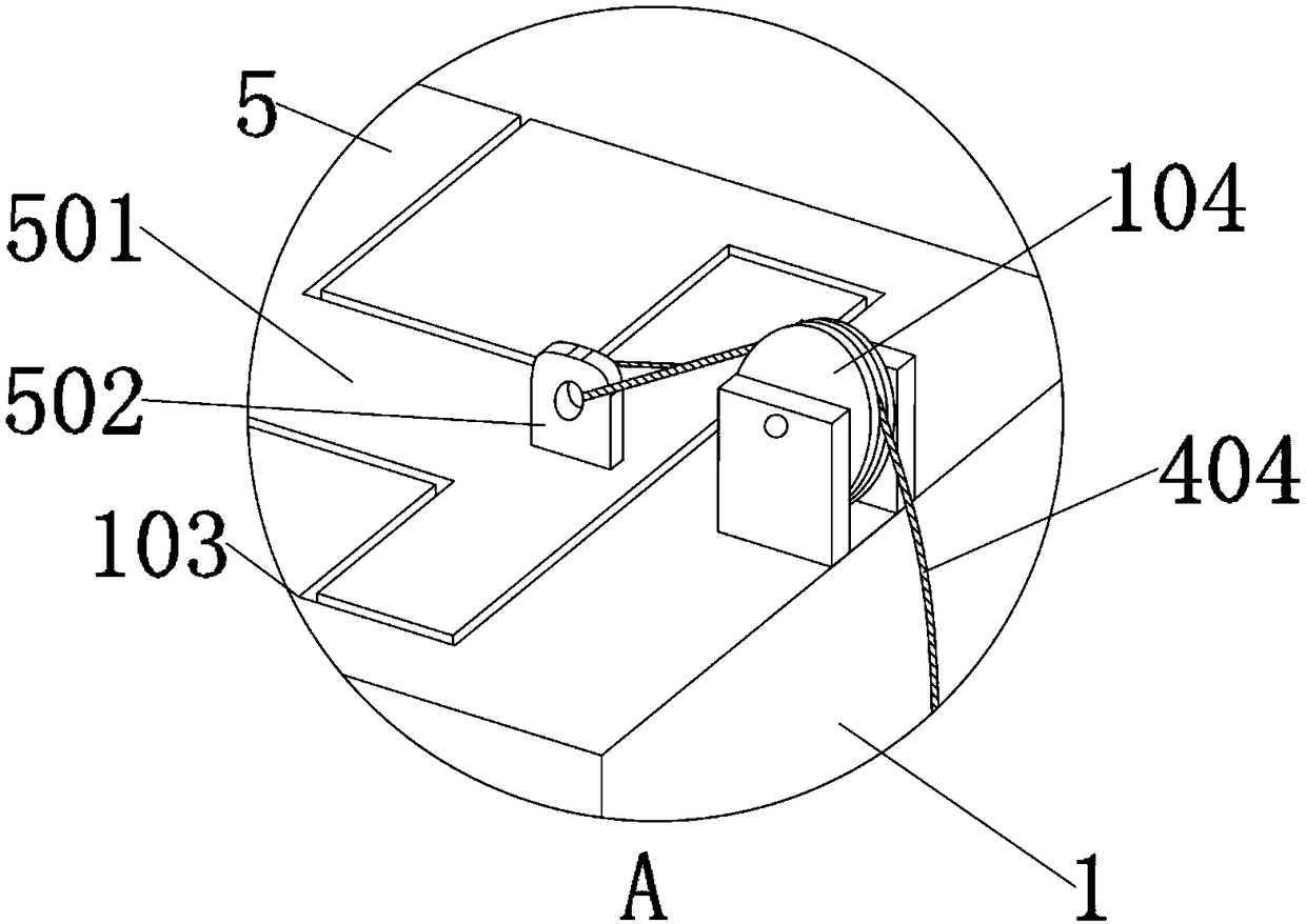
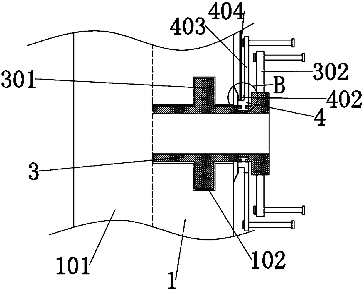
[0032]The present invention provides a device for limiting the width of road bridges, including: a main body 1, an embedded groove 101, a fixed groove 102, an installation groove 103, a guide wheel 104, a bottom plate 105, a limit groove 106, a moving part 2, and an anti-slip pad 201 , moving wheel 202, tension spring 203, moving shaft 204, rotating part 3, inserting part 301, rotating rod 302, inserting chute 303, tensioning part 4, winding groove 401, guiding part 402, manual lever 403, traction rope 404, push rod 5, embedded head 501, connector 502, closed groove 503, flip plate 6, support spring 601, limiter 7, pull rod 701 and outer support spring 702; main body 1 is a rectangular strip structure, and Both sides of the bottom of the main body 1 are installed with a base plate 105 by welding, and the inside of the base plate 105 is connected to the nut of the ground through bolts, and the middle position of both si...


PUM


Abstract

A road bridge width limiting device is composed of a flip plate, a support spring, a limit member, a pull rod and an outer support spring. The bottom of the moving part is mounted with a moving wheelthrough a connecting part and a rotating shaft, and the outside of the moving shaft is provided with threads, and the moving shaft is installed in the inside of the rotating part through threads; theinsert on the inner side of the tensioning member is installed inside the insert sliding groove on the inner side of the rotating member in an inserting manner, and a manual lever is mounted on the outer edge position of the tension member by welding, and the outer end of the manual lever is provided with a limited position lever through a mounting hole. The rotating part here plays the rotationalpower transmitted by the receiving manpower., the rotating member transmits the power to the moving shaft through the internal thread, so that the moving shaft drives the moving member to move to different positions, thereby limiting the width of the road or the bridge, and the insert in the middle position of the rotating member is embedded into the inside of the fixed groove installed in the middle position of the main body.

Description

technical field [0001] The invention belongs to the technical field of width limiting devices and road facilities, and more specifically relates to a width limiting device for road bridges. Background technique [0002] There will be a width-limiting door at the head end of the road or bridge to prevent heavy or special vehicles from entering the road and causing damage, or entering the bridge, so that the bridge cannot bear the load and breaks. [0003] For example, the application number: CN201610441759.2 relates to a road bridge width limiting device, including a pre-buried underground base, characterized in that: the upper surface of the base is provided with grooves, and the bases on both sides of the groove are provided with A support block, the top of the support block is provided with a beam, the upper surface of the beam is provided with a chute, a slider is embedded in the chute, a support column is provided on the slider, and the chute in the chute Through holes ...

Claims


Application Information

Patent Timeline
IPC IPC(8): E01F13/04
CPCE01F13/048
Inventor 杨喜成
Owner 绍兴市卓诚新材料有限公司
Why Eureka
Try Eureka