
Electric drive speed changing structures and automobile

A technology of variable speed structure and electric drive, applied in the direction of transmission device, gear transmission device, belt/chain/gear, etc., can solve the problems of reducing the comfort of the driver, complicated control method of the speed change structure, etc., and achieve the effect of improving comfort.

Pending Publication Date: 2019-01-01
SCHAEFFLER TECH AG & CO KG
View PDF5 Cites 0 Cited by
  • Summary
  • Abstract
  • Description
  • Claims
  • Application Information

AI Technical Summary

Problems solved by technology

However, using a synchronizer to adjust the gear position will reduce the comfort of the driver, and it will also make the control method of the transmission structure more complicated.

Method used


Image

  • Electric drive speed changing structures and automobile
  • Electric drive speed changing structures and automobile

Examples


no. 1 example

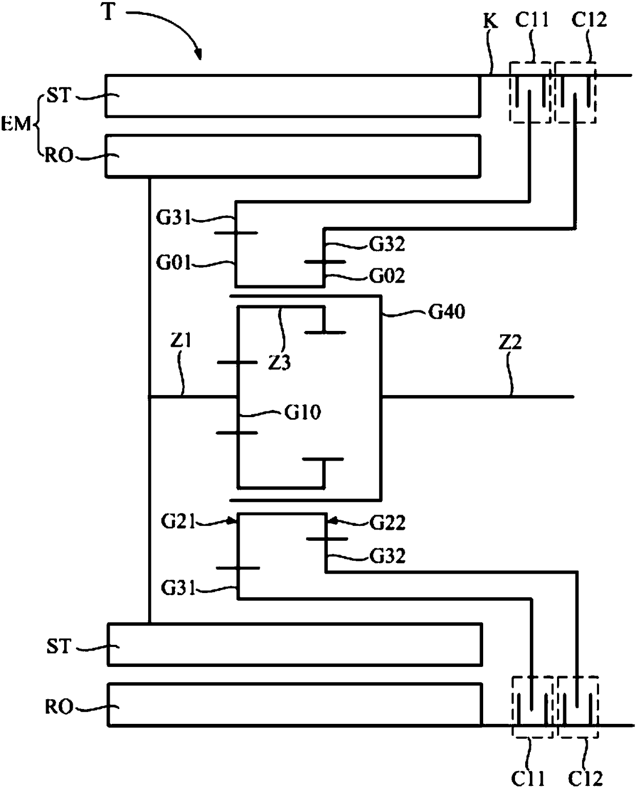
[0025] refer to figure 1 , an electric drive transmission structure T, including a housing K and an input shaft Z1 and an output shaft Z2 arranged in the housing K. The input shaft Z1 is used as a power input end for connecting with a driving motor or an engine; the output shaft Z2 is used as a power output end for connecting with a drive shaft or a differential.

[0026] The electric drive transmission structure T also includes a sun gear G10, a first planetary gear set G21 and a second planetary gear set G22 arranged in sequence along the axial direction, a first ring gear G31 and a second ring gear G32 arranged in sequence along the axial direction and A first brake C11 and a second brake C12 are arranged in sequence in the axial direction.

[0027] Wherein, all the planetary gears in the first planetary gear set G21 are distributed along the circumferential direction, and the first planetary gear set G21 is located between the sun gear G10 and the first ring gear G31, mes...

no. 2 example

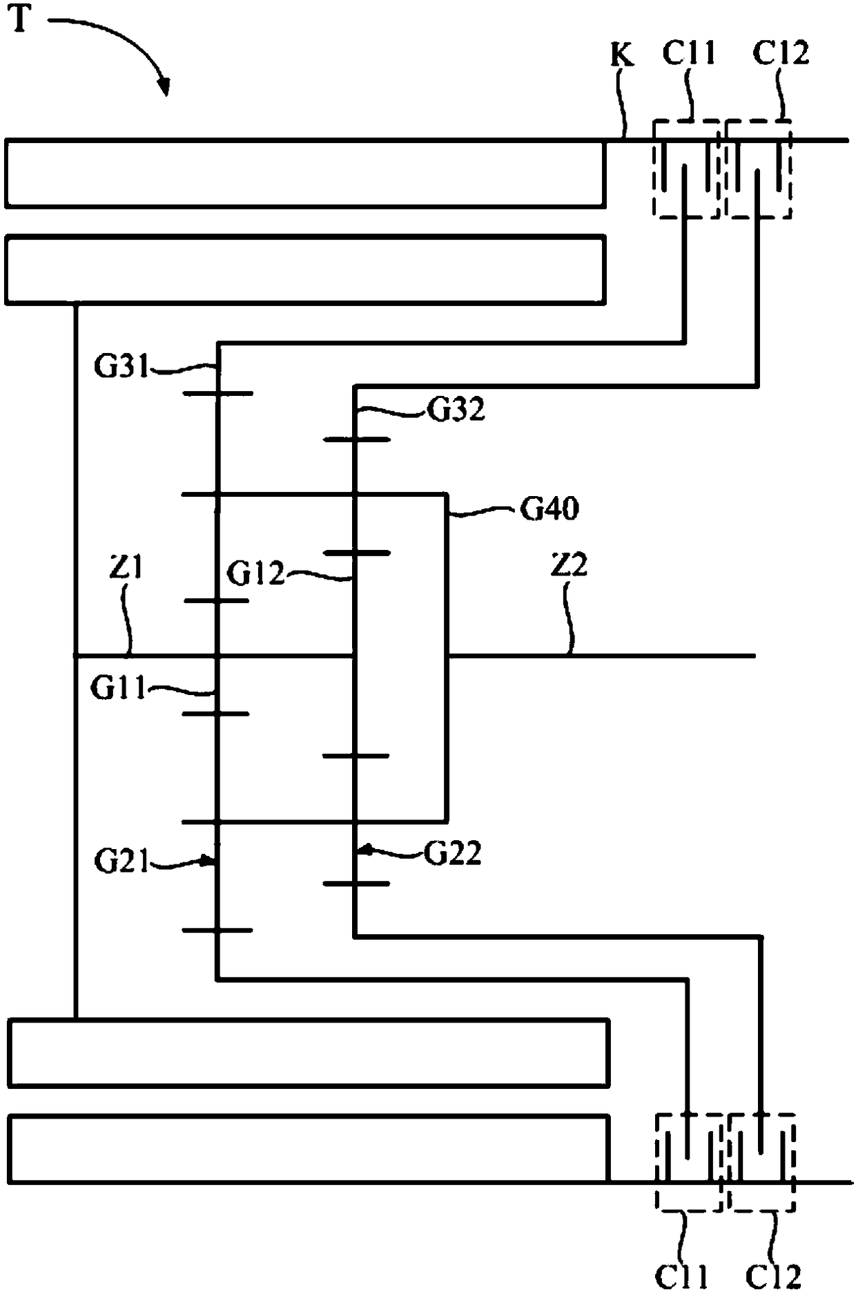
[0057] refer to figure 2 , The difference between this embodiment and the first embodiment is that the electric drive transmission structure T includes two sun gears: the first sun gear G11 and the second sun gear G12 along the axial direction, the first sun gear G11 and the second sun gear G11 Both sun gears G12 are fixedly arranged on the input shaft Z1.

[0058] Among them, the first sun gear G11, the first planetary gear set G21 and the first ring gear G31 are meshed sequentially from inside to outside to form the first planetary row, and the second sun gear G12, the second planetary gear set G22 and the second gear The rings G32 mesh sequentially from inside to outside to form the second planetary row.

[0059] Both the first planetary gear set G21 and the second planetary gear set G22 are fixedly connected to the planet carrier G40, and the planet carrier G40 is fixedly connected to the output shaft Z2. At this time, the planetary gears in the first planetary gear set...


PUM


Abstract

The invention discloses an electric drive speed changing structure and an automobile. The electric drive speed changing structure includes a shell, an input shaft and an output shaft, and further includes a sun gear fixedly connected with the input shaft, multiple planet gear sets disposed in an axial direction, multiple gear rings disposed in the axial direction, a planet carrier fixedly connected to the output shaft, and multiple brakes. One planet gear set of the multiple planet gear sets is engaged with the sun gear; the gear rings and the planet gear sets are correspondingly disposed andengaged; the planet gear sets are fixedly connected with the planet carrier; and the brakes are disposed corresponding to the gear rings, and used for jointing or separating the gear rings and the shell. When a driving motor operates and a gear position needs to be changed, the brakes are controlled to make the different brakes joint or separate with the corresponding gear rings to achieve a purpose of shifting gears; and gear shifting is achieved through the brakes, so that a condition does not occur that the power of the driving motor cannot be transmitted to the output shaft for a long period of time during a gear shifting process, and so, comfortableness of drivers can be improved.

Description

technical field [0001] The invention relates to the technical field of automobiles, in particular to an electric drive variable speed structure and an automobile. Background technique [0002] With the requirements of environmental protection and fuel saving, electric vehicles and hybrid vehicles are attracting more and more attention. Electric vehicles and hybrid vehicles are generally provided with a drive motor, and the drive motor can usually drive the vehicle alone. In order to improve the working efficiency of the driving motor, electric vehicles and hybrid vehicles are equipped with an electric drive variable speed structure, so that the vehicle can also run in different gears under the drive of the driving motor. [0003] In the prior art, the electric drive transmission structure usually includes gears and synchronizers. The driving motor transmits power to the gears. By controlling the movement of the synchronizer, the synchronizer is engaged with different gears ...

Claims


Application Information

Patent Timeline
Patent Type & Authority Applications(China)
IPC IPC(8): F16H3/44F16H3/58
CPCF16H3/44F16H3/58
Inventor 赵晓峰
Owner SCHAEFFLER TECH AG & CO KG
Learn More