Storage rack

A rack and smooth technology, applied in the field of racks, can solve the problems of inability to realize multiple sets of drilling operations, single setting mode, and reduce processing efficiency, so as to improve the drilling efficiency and drilling effect, and the device structure is simple and automatic high degree of effect

Inactive Publication Date: 2019-01-04
广州吉和电子商务有限公司
View PDF5 Cites 0 Cited by
  • Summary
  • Abstract
  • Description
  • Claims
  • Application Information

AI Technical Summary

Problems solved by technology

[0002] Shelves are widely used in real life. Shelves are generally assembled with multiple metal plates, and these metal plates need to be punched during production. The traditional punching device has a single setting mode. And it requires too much manpower to be put into use, and at the same time it cannot realize multiple groups of drilling operations on the same line, which greatly reduces the processing efficiency, has great disadvantages, and needs to be improved

Method used


Image

  • Storage rack
  • Storage rack
  • Storage rack

Examples


Embodiment Construction

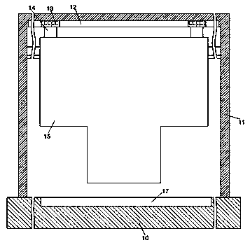
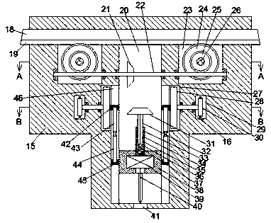
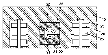
[0018] Such as Figure 1-4 As shown, a storage rack of the present invention includes a base body 10, a support plate 11 fixedly arranged on the top end surface of the base body 10, and a casing 15 smoothly installed on the support plate 11. The casing The body 15 is provided with a first smooth groove 20 extending up and down, and transparent grooves 46 are symmetrically arranged in the left and right end walls of the first smooth groove 20, and a slide table 38 is smoothly installed in the first smooth groove 20. A first motor 39 is fixedly installed in the slide table 38, a drill bit 40 extending downward is installed on the bottom end of the first motor 39, and a steering sleeve 33 extending upward is installed on the top end of the first motor 39. The steering sleeve 33 is provided with a spline groove 34 with an upward mouth. The spline shaft 32 is fitted with a spline in the spline groove 34. The top of the spline shaft 32 is fixed with a first tapered wheel 31. The en...


PUM


Abstract

The invention discloses a storage rack. The storage rack comprises a base body, a support plate fixedly arranged on the top end surface of the base body and a machine shell arranged on the support plate in a horizontal sliding manner. A first horizontal sliding groove extending up and down is formed in the machine shell. Through grooves are symmetrically formed in the left end wall and the right end wall of the first horizontal sliding groove. A sliding table is arranged in the first horizontal sliding groove in a horizontal sliding manner. A first motor is fixedly arranged in the sliding table. A drilling bit extending downwards is arranged on the bottom end surface of the first motor in a power manner. An upward extending steering sleeve is arranged on the top end surface of the first motor in a power manner. A spline groove with an upward opening is formed in the steering sleeve. A spline shaft is arranged in the spline groove in a spline fit manner. A first tapered wheel is fixedlyarranged at the top of the spline shaft. First connecting seats which extend into the through grooves and are in horizontal sliding fit connection are symmetrically arranged on the left end surface and the right end surface of the sliding table.

Description

technical field [0001] The invention relates to the technical field of storage racks, in particular to a storage rack. Background technique [0002] Shelves are widely used in real life. Shelves are generally assembled with multiple metal plates, and these metal plates need to be punched during production. The traditional punching device has a single setting mode. And it requires too much manpower to be put into use, and it is impossible to realize multiple groups of drilling operations on the same straight line, which greatly reduces the processing efficiency, has relatively large drawbacks, and needs to be improved. Contents of the invention [0003] The technical problem to be solved by the present invention is to provide a storage rack, which can solve the above-mentioned problems in the prior art. [0004] The present invention is achieved through the following technical solutions: a shelf of the present invention includes a base body, a support plate fixed on the to...

Claims


Application Information

Patent Timeline
Patent Type & Authority Applications(China)
IPC IPC(8): B23B41/00B23B47/00
CPCB23B41/00B23B47/00
Inventor 余小兰
Owner 广州吉和电子商务有限公司
Why Eureka
Try Eureka