Radar sensor type safety corridor system
A technology of radar sensing and safety corridor, which is applied in radio wave measurement system, sensing radiation of moving objects, reflection/re-radiation of radio waves, etc. It can solve problems such as easy entry into dangerous state, death, life danger of sick and weak people, etc.
- Summary
- Abstract
- Description
- Claims
- Application Information
AI Technical Summary
Problems solved by technology
Method used
Image
Examples
Embodiment 1
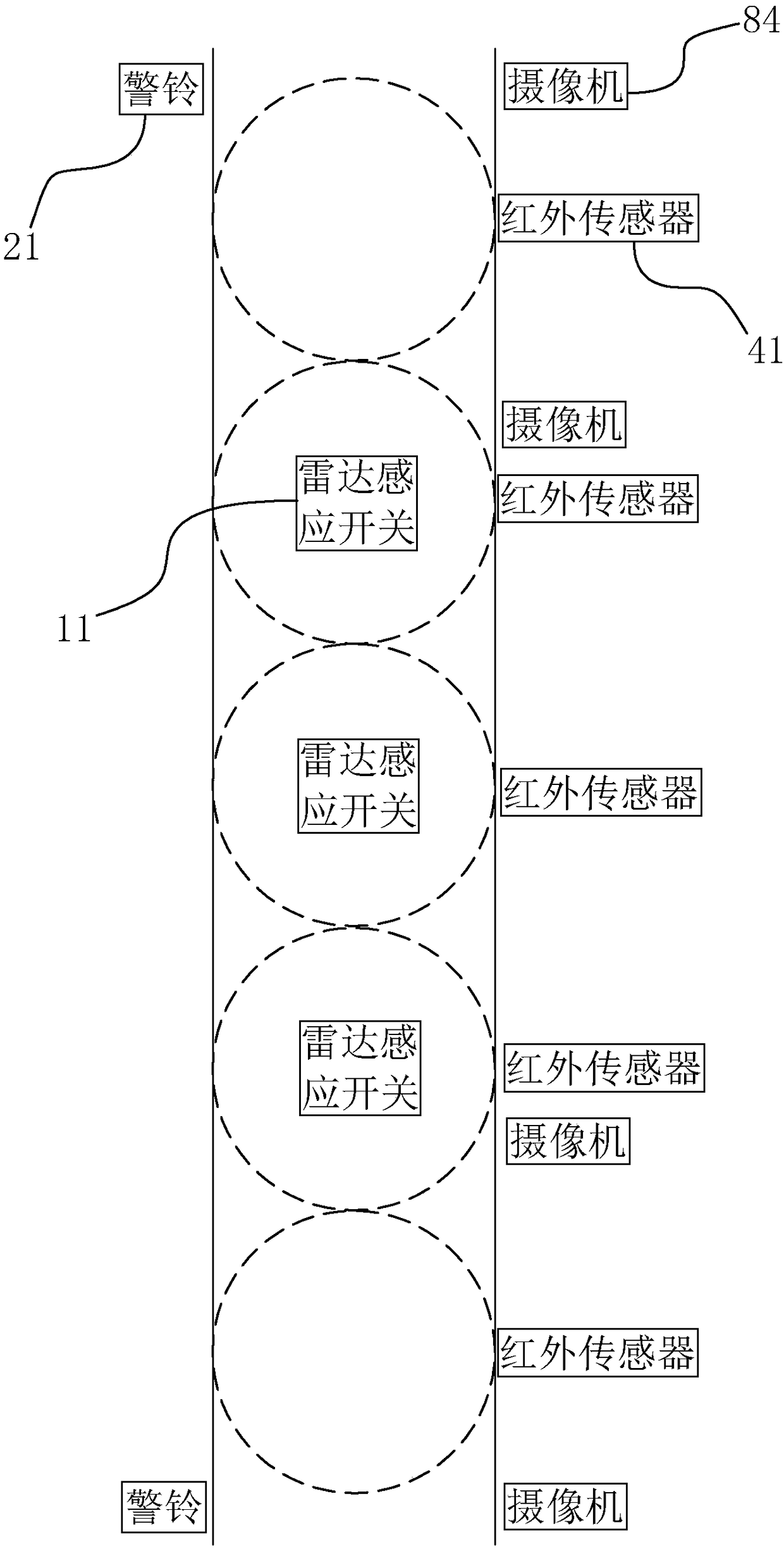
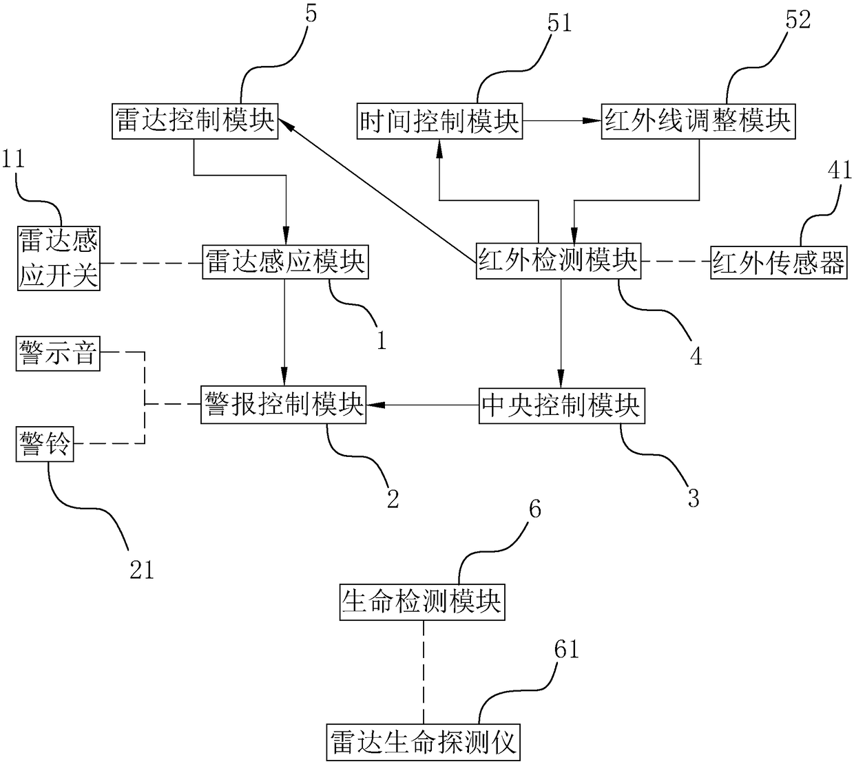
[0046] Embodiment 1: A radar-inductive safety corridor system, such as figure 1 and figure 2 As shown, it includes a radar sensing module 1 , an alarm control module 2 , a central control module 3 and an infrared detection module 4 . The radar sensing module 1 includes a plurality of radar sensing switches 11 evenly distributed in the corridor. The boundaries of the sensing areas of every two adjacent radar sensing switches 11 are in contact with each other, so that the detection range of the radar sensing switches 11 can be continuous in the corridor. All the radar sensor switches 11 are numbered respectively, and the numbers are arranged according to the order of the radar sensor switches 11 along the length direction of the corridor. When any radar sensor switch 11 detects a dynamic object, the numbered alarm signal is transmitted to the alarm control module 2 .
[0047] Such as figure 2 As shown, the alarm trigger module is connected to the radar sensing module 1, an...
Embodiment 2
[0057] Embodiment 2: A radar-inductive safety corridor system, such as Figure 5 and Figure 6 As shown, the difference with Embodiment 1 is that the central control module 3 is connected with an ultrasonic detection module 9, and the ultrasonic detection module 9 includes an ultrasonic sensor 91 installed on the corridor corresponding to each infrared sensor 41 position, and each ultrasonic sensor The detection ranges of 91 are all the same as the detection ranges of the corresponding infrared sensors 41 . Each ultrasonic sensor 91 has the same reference number as the corresponding infrared sensor 41 . A stop signal is output when the ultrasonic sensor 91 detects an object. After the central control module 3 receives the alarm signal, the central control module 3 receives the stop signal output by the ultrasonic sensor 91 whose number is adjacent to the alarm signal. When the central control module 3 receives the stop signal output by the ultrasonic sensor 91 whose number ...
PUM
 Abstract
Description
Claims
Application Information
 - R&D
- Intellectual Property
- Life Sciences
- Materials
- Tech Scout
- Unparalleled Data Quality
- Higher Quality Content
- 60% Fewer Hallucinations
Browse by: Latest US Patents, China's latest patents, Technical Efficacy Thesaurus, Application Domain, Technology Topic, Popular Technical Reports.
© 2025 PatSnap. All rights reserved.Legal|Privacy policy|Modern Slavery Act Transparency Statement|Sitemap|About US| Contact US: help@patsnap.com


