A multi-channel LED dimming circuit

A dimming circuit and dimming technology, applied in the field of power electronics, can solve the problems of unstable current, limited dimming accuracy, and inability to fully realize it, and achieve the effects of suppressing overshoot current, improving dimming accuracy, and avoiding flickering

Active Publication Date: 2019-12-03
XIDIAN UNIV
View PDF5 Cites 0 Cited by
  • Summary
  • Abstract
  • Description
  • Claims
  • Application Information

AI Technical Summary

Problems solved by technology

[0004] However, in this method of multi-channel LED dimming control circuit, the dimming accuracy of 0-100% cannot be achieved, the dimming range is limited, and the current will be unstable, causing the LED lights to flicker
In this mode of LED drive circuit with multi-channel dimmable constant current output, its dimming accuracy is limited, and it cannot fully realize 0-100% dimming

Method used


Image

  • A multi-channel LED dimming circuit
  • A multi-channel LED dimming circuit
  • A multi-channel LED dimming circuit

Examples


Embodiment 1

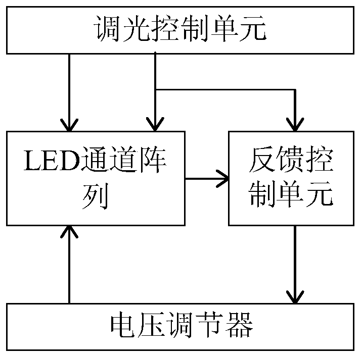
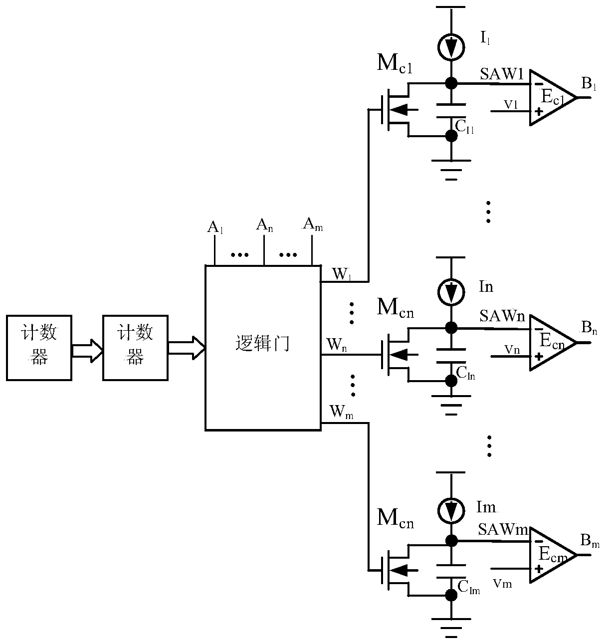
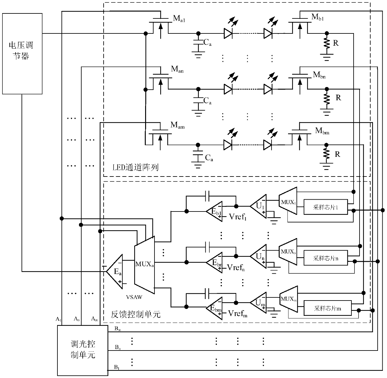
[0055] See figure 1 , figure 2 , image 3 and Figure 4 , figure 1 A schematic diagram of module connection of a multi-channel LED dimming circuit provided by the present invention; figure 2 A schematic diagram of the circuit structure of a dimming control unit of a multi-channel LED dimming circuit provided by the present invention; image 3 A schematic diagram of the circuit structure of a multi-channel LED dimming circuit provided by the present invention; Figure 4 A circuit waveform diagram of a multi-channel LED dimming circuit provided by the present invention.

[0056] like figure 1 As shown, a multi-channel LED dimming circuit includes: a dimming control unit, a feedback control unit, a voltage regulator and an LED channel array; wherein,

[0057] The first output terminal of the dimming control unit is respectively connected to the first input terminal of the LED channel array and the first input terminal of the feedback control circuit, and the second outpu...


PUM


Abstract

The invention relates to a multi-channel LED dimming circuit, comprising: a dimming control unit, a feedback control unit, a voltage regulator and an LED channel array; wherein, the first output terminals of the dimming control unit are respectively connected to the first input of the LED channel array terminal and the first input terminal of the feedback control circuit, the second output terminal of the dimming control circuit is connected to the second input terminal of the LED channel array; the first output terminal of the feedback control unit is connected to the input terminal of the voltage regulator; the voltage regulator’s The output end is connected to the third input end of the LED channel array; the output end of the LED channel array is connected to the second input end of the feedback control unit. The invention can effectively suppress the overshoot current of the LED when the dimming MOS tube is turned on, so that the current flowing through the LED lamp string is more stable, prolongs the service life of the LED lamp, and avoids the flickering of the LED lamp.

Description

technical field [0001] The invention belongs to the field of power electronics, and in particular relates to a multi-channel LED dimming circuit. Background technique [0002] In recent years, LEDs (Light Emitting Diodes) have been widely used as green, energy-saving, and long-life light-emitting products. Compared with traditional lighting sources, LED has obvious advantages. LED is essentially a semiconductor diode with typical PN junction volt-ampere characteristics, that is, the current of the LED does not change linearly with the voltage. Therefore, it is not possible to directly use a voltage source to supply power to the LED, and it is necessary to control the magnitude of the current flowing through the LED. In daily LED lighting applications, in different environments, LED lights need to adjust different brightness to meet the different needs of different people for brightness. Therefore, the brightness of LED light can be adjusted by adjusting the average current...

Claims


Application Information

Patent Timeline
Patent Type & Authority Patents(China)
IPC IPC(8): H05B33/08H05B44/00
CPCH05B45/10
Inventor 张艺蒙屈莎莎张玉明宋庆文汤晓燕
Owner XIDIAN UNIV
Why Eureka
Try Eureka