Drainage device for hydraulic engineering

A water conservancy project, No. 1 technology, applied in applications, irrigation pipes, buildings, etc., can solve the problems of large filter screen resistance, no diversion structure, easy silting, etc., to avoid waste of manpower and material resources, improve effective working time, The effect of reducing the number of repairs

Active Publication Date: 2019-01-08
江苏微纳光膜科技有限公司
View PDF5 Cites 5 Cited by
  • Summary
  • Abstract
  • Description
  • Claims
  • Application Information

AI Technical Summary

Problems solved by technology

[0002] The water conservancy drainage device is a kind of equipment that controls the flow direction of the water flow according to the user's needs. The user can guide the water flow to other directions through the water conservancy drainage device, and can fully utilize the existing hydraulic resources through the water conservancy drainage device. It has certain beneficial effects on farmland irrigation, aquaculture, etc.; the existing water conservancy drainage device has certain disadvantages when it is used. The traditional water conservancy drainage device itself does not have a diversion structure, and the drainage structure of the water conservancy drainage device is single. The flow direction of the water is modified twice. The traditional water drainage device is prone to blockage during long-term use, which increases the number of maintenance of the water drainage device. During the drainage process, special personnel are required to take care of it, which wastes manpower and material resources. Ordinary filter screens have high resistance and are easy to silting, for this reason, we propose a drainage device for hydraulic engineering

Method used


Image

  • Drainage device for hydraulic engineering
  • Drainage device for hydraulic engineering
  • Drainage device for hydraulic engineering

Examples


Embodiment Construction

[0030] In order to make the purpose, technical solution and advantages of the present invention clearer, the technical solution of the present invention will be described in detail below. Apparently, the described embodiments are only some of the embodiments of the present invention, but not all of them. Based on the embodiments of the present invention, all other implementations obtained by persons of ordinary skill in the art without making creative efforts fall within the protection scope of the present invention.

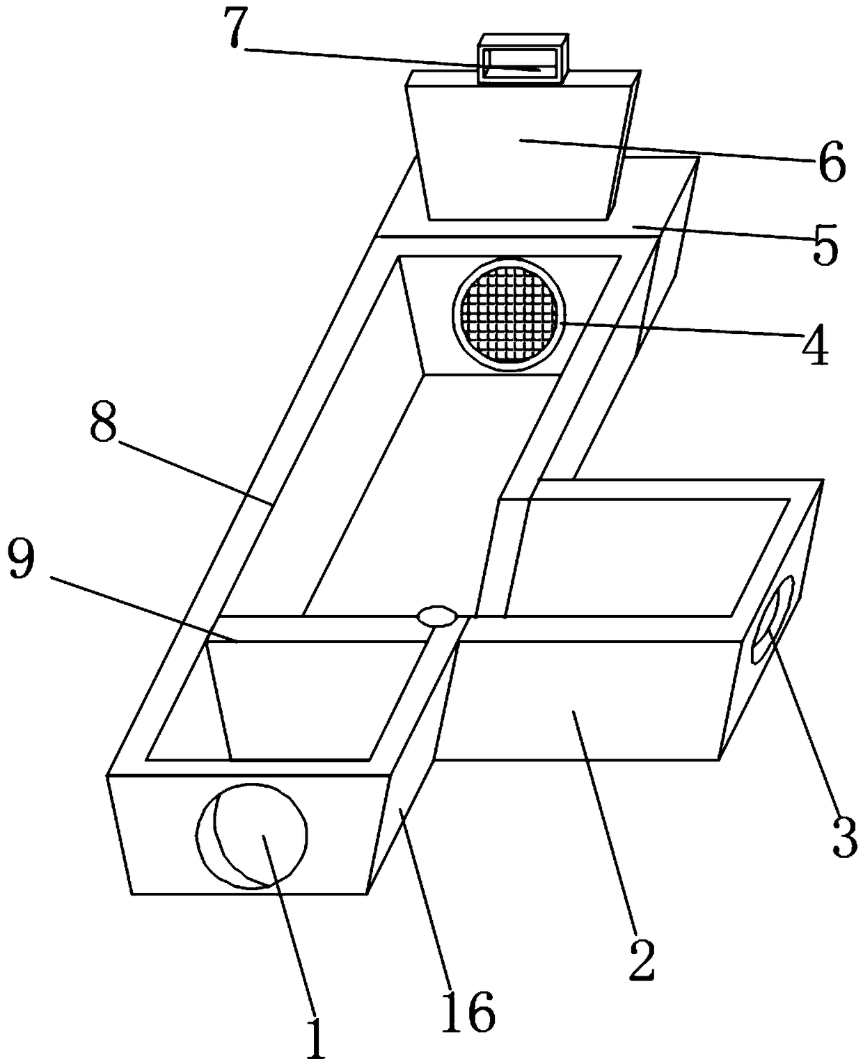
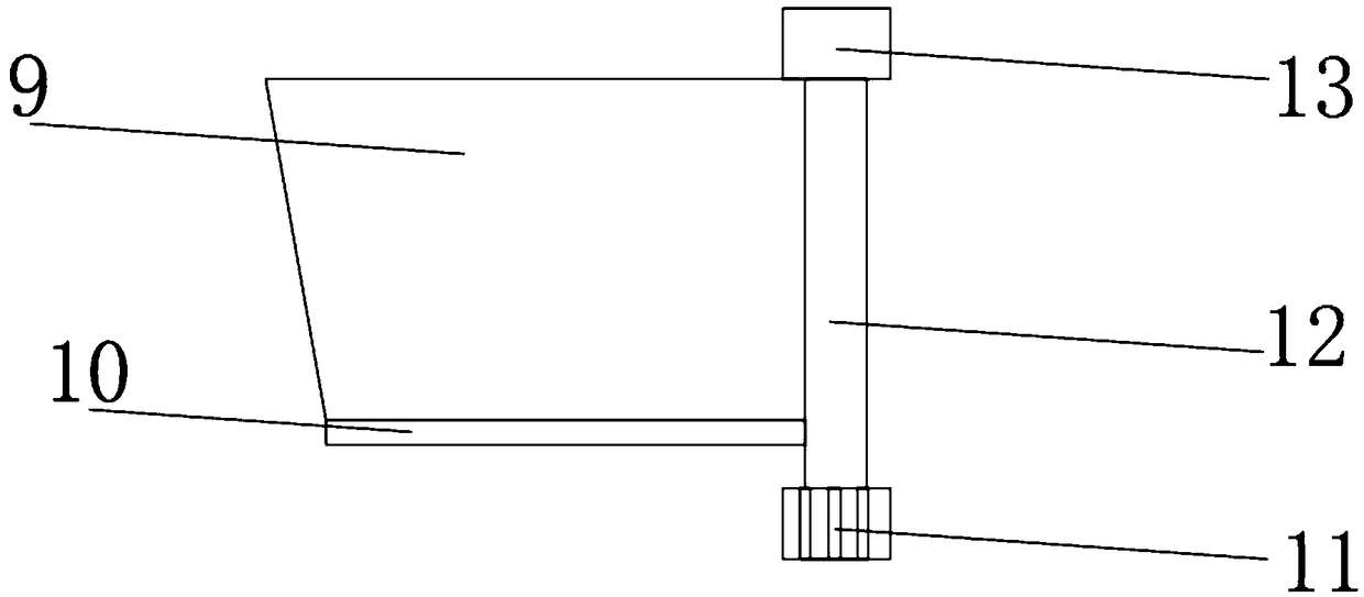
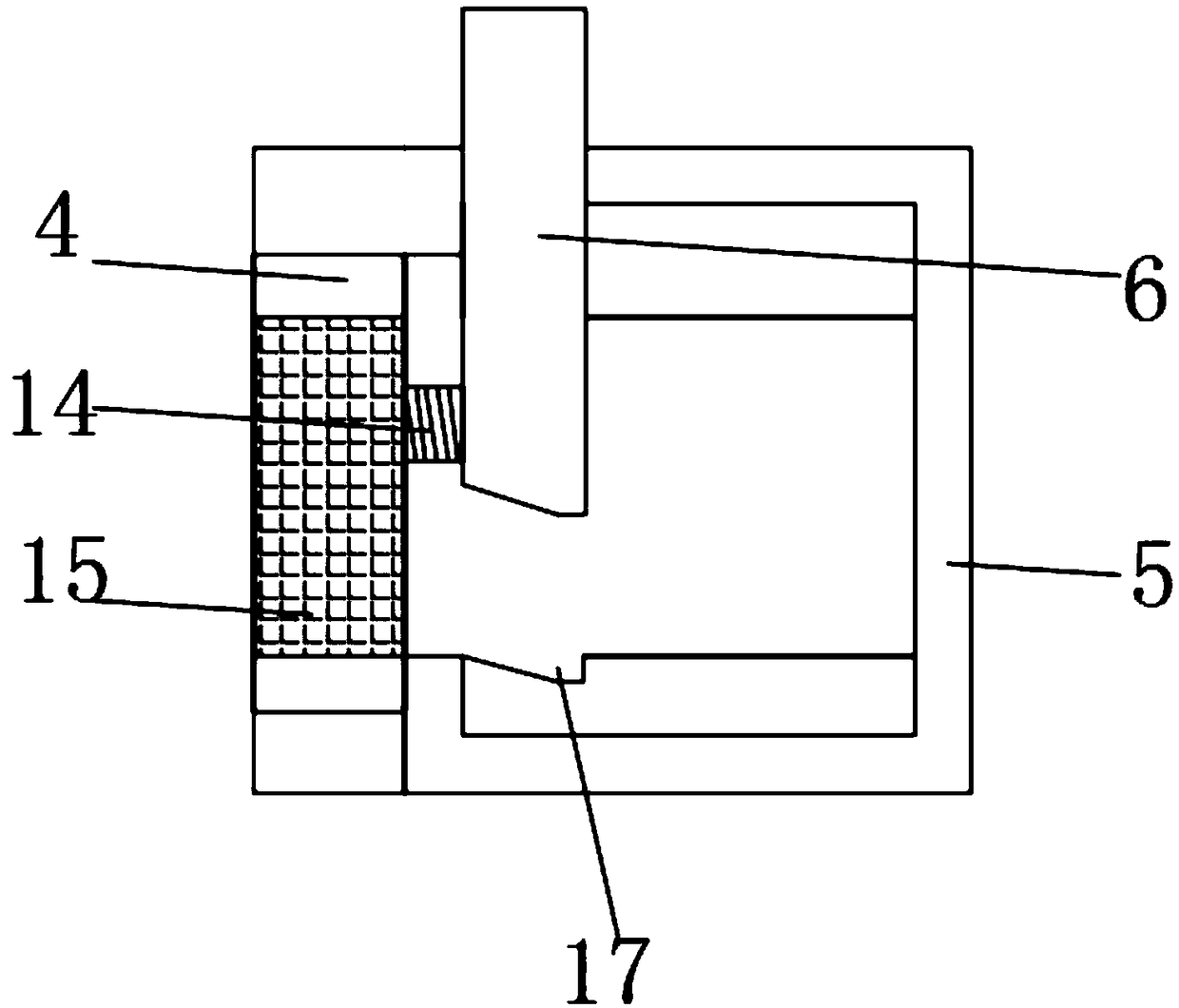
[0031] see Figure 1-Figure 3 As shown, the invention provides a drainage device for water conservancy engineering, comprising:

[0032] Drainage canal, the drainage canal comprises a drainage device main body 8, the rear end inner surface of the drainage device main body 8 is fixedly equipped with a filter water inlet pipe 4, and the rear end outer surface of the drainage device main body 8 is fixedly equipped with an intercepting pier 5, so The upper outer s...


PUM


Abstract

The invention discloses a drainage device for hydraulic engineering. The drainage device comprises a drainage channel; the drainage channel comprises a drainage device main body; a filter water inletpipe is fixedly mounted on the inner surface of the rear end of the drainage device main body; the outer surface of the rear end of the drainage device main body is fixedly provided with a closure pier; the outer surface of the upper end of the closure pier is movably provided with a closure baffle; a sealing groove is formed in the position, close to the lower portion of the closure baffle, of the inner surface of the interior of the closure pier; a cleaning bristle brush is fixedly mounted on the outer surface of the side, close to the closure baffle, in the closure pier; and a filter mesh is fixedly mounted on the inner surface of the interior of the filter water inlet pipe. In summary, the drainage device has the beneficial effects that the drainage device for hydraulic engineering adopts the filter water inlet pipe and a drainage mechanism, the drainage effect of the device can be improved, the blockage phenomenon of the device is avoided, the maintenance frequency of the device is lowered, and the device is simple in structure and convenient to use.

Description

technical field [0001] The invention relates to the field of water conservancy engineering equipment, in particular to a drainage device for water conservancy engineering. Background technique [0002] The water conservancy drainage device is a kind of equipment that controls the flow direction of the water flow according to the user's needs. The user can guide the water flow to other directions through the water conservancy drainage device, and can fully utilize the existing hydraulic resources through the water conservancy drainage device. It has certain beneficial effects on farmland irrigation, aquaculture, etc.; the existing water conservancy drainage device has certain disadvantages when it is used. The traditional water conservancy drainage device itself does not have a diversion structure, and the drainage structure of the water conservancy drainage device is single. The flow direction of the water is modified twice. The traditional water drainage device is prone to ...

Claims


Application Information

Patent Timeline
Patent Type & Authority Applications(China)
IPC IPC(8): E02B13/00E02B13/02
CPCE02B13/00E02B13/02
Inventor 王真
Owner 江苏微纳光膜科技有限公司
Why Eureka
Try Eureka