A high pressure water well valve for oil field

A high-pressure, water well technology, applied in the direction of wellbore/well valve device, wellbore/well parts, sealing/packing, etc., can solve the problems of springback fatigue, poor stability, screw plugging, etc., to improve service life, Improve stability, control labor-saving effect

Active Publication Date: 2019-05-03
DAQING TIANDEZHONG PETROLEUM SCI & TECH CO LTD
View PDF8 Cites 0 Cited by
  • Summary
  • Abstract
  • Description
  • Claims
  • Application Information

AI Technical Summary

Problems solved by technology

[0003] High-pressure water well valves used in oil fields are mainly used to control the transmission of oil pipes. Since oil pipes are mostly buried under the oil field, the working environment of high-pressure water well valves used in oil fields is harsh. The existing high-pressure water well valves used in oil fields have the following defects in actual use: 1. Some high-pressure water well valves used in oil fields mostly control the lifting and lowering of the valve stem through the screw. The mud and sand in the oil field may be brought into the screw during the rotation of the valve stem, causing the screw to block and affecting the normal operation and stability of the valve. Poor; 2. The return springs of the existing high-pressure water well valves used in oil fields are mostly located inside the valve. After repeated use, rebound fatigue is prone to occur, which affects the service life of the valve; 3. In winter, the water content of the oil field is high. The valve is easy to freeze, causing the valve stem to fail to control the valve core switch normally, affecting the normal transmission of the oil pipe

Method used


Image

  • A high pressure water well valve for oil field
  • A high pressure water well valve for oil field
  • A high pressure water well valve for oil field

Examples


Embodiment Construction

[0024] The following will clearly and completely describe the technical solutions in the embodiments of the present invention with reference to the accompanying drawings in the embodiments of the present invention. Obviously, the described embodiments are only some, not all, embodiments of the present invention.

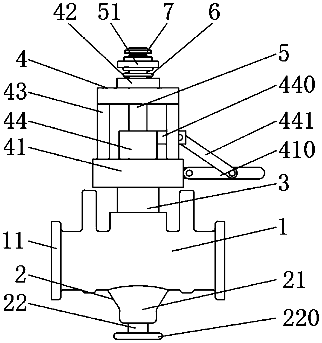
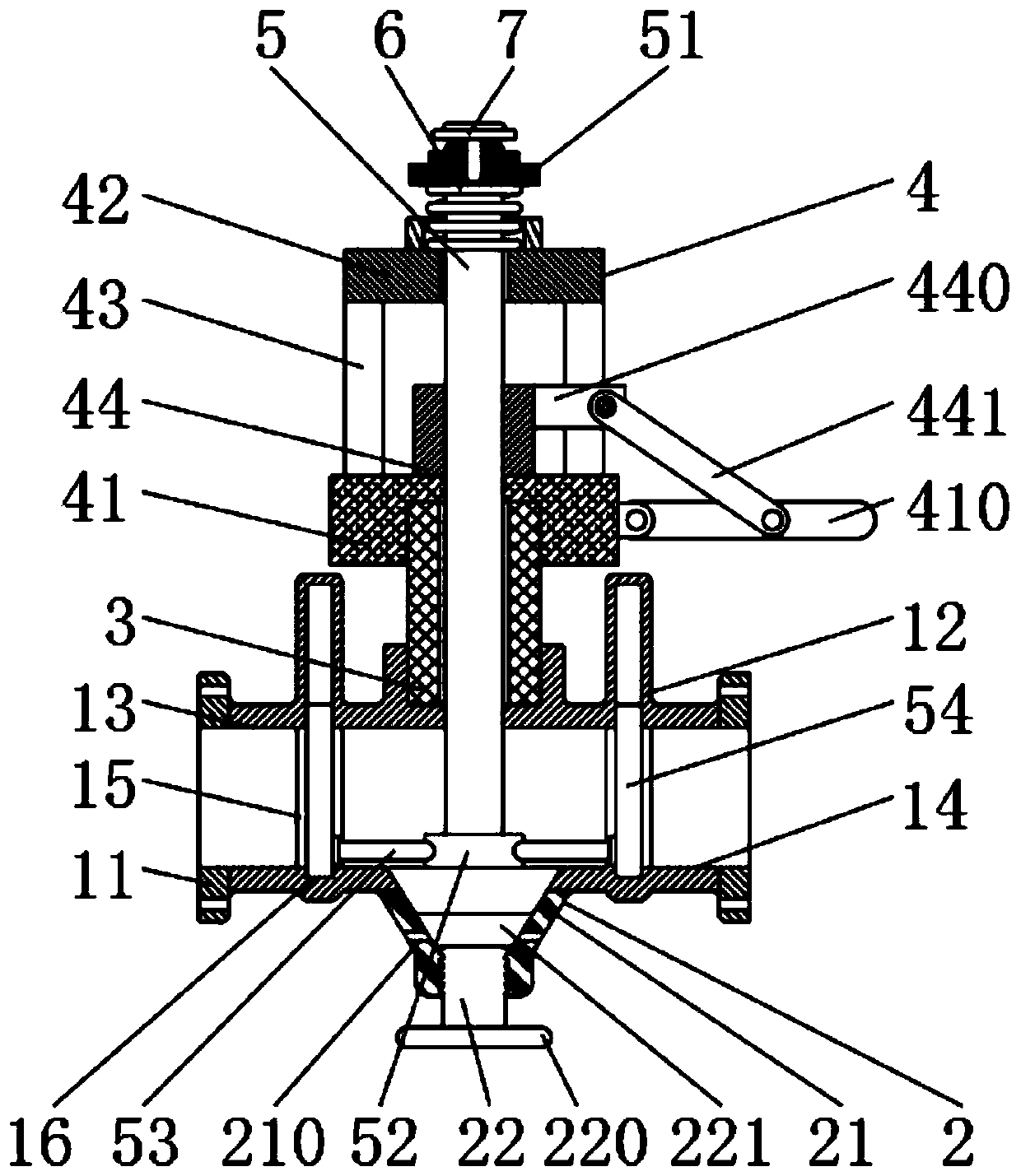
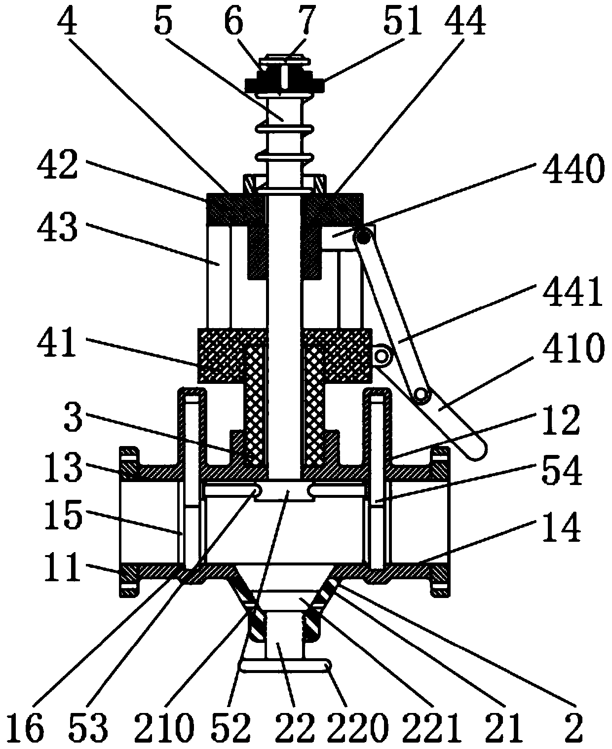
[0025] see Figure 1 to Figure 5, the present invention provides a technical solution: a high-pressure water well valve for oil fields, comprising a valve body 1 with an oil inlet 13 and an oil outlet 14 respectively opened at both ends, and an oil drain part 2 fixedly connected to the bottom of the valve body 1, The valve seat 4 fixedly installed on the top of the valve body 1 and the valve stem 5 passing through the valve seat 4 and extending to the inner cavity of the valve body 1, the inner side wall of the valve body 1 is fixedly connected with the guide rail 15, and the lower inner side wall of the valve body 1 is opened There is a sealing groove 16, and the to...


PUM


Abstract

The invention discloses a high-pressure water well valve for an oil field and relates to the technical field of valves. The high-pressure water well valve specifically comprises a valve body with an oil inlet and an oil outlet at two ends, an oil drainage portion fixedly connected to the bottom of the valve body, a valve seat fixedly installed above the valve body and a valve rod extending to a valve body cavity. An inner side wall of the valve body is fixedly connected with a guide rail, and a lower inner side wall of the valve body is provided with a sealing groove. According to the high-pressure water well valve for the oil field, by setting a driving crank, a driven crank and a pressure sleeve for cooperation, the lever principle is used, the driving crank is pressed, the driven crankcan be driven to rotate downward, therefore, the pressure sleeve pulls the valve rod to move upward along a guide sleeve, the lifting and lowering of the valve rod are controlled, the spiral control is not needed, a problem that soil and sand in an oil field may be brought into a spiral during the rotation of the valve rod to cause spiral blocking and affect the normal working of the valve is avoided, and the stability of the working of the water well valve is effectively improved.

Description

technical field [0001] The invention relates to the technical field of valves, in particular to a high-pressure water well valve for oil fields. Background technique [0002] High-pressure valves have been widely used in the fields of superhard material manufacturing, chemical industry, petrochemical industry, processing technology, isostatic pressure treatment, ultra-high static pressure extrusion, powder metallurgy, metal forming, and geophysical and geological research. Control the flow of various types of fluids such as air, water, steam, various corrosive media, mud, oil, liquid metal and radioactive media. The opening and closing part is a disc-shaped valve plate, which wraps around its own The axis rotates to achieve the purpose of opening and closing or adjustment. [0003] High-pressure water well valves used in oil fields are mainly used to control the transmission of oil pipes. Since oil pipes are mostly buried under the oil field, the working environment of high...

Claims


Application Information

Patent Timeline
Patent Type & Authority Patents(China)
IPC IPC(8): E21B34/06
CPCE21B34/06
Inventor 张淞源张虎
Owner DAQING TIANDEZHONG PETROLEUM SCI & TECH CO LTD
Why Eureka
Try Eureka