Unmanned aerial vehicle grabbing device

A technology for grabbing objects and mounting racks, which is used in motor vehicles, aircraft parts, transportation and packaging, etc. It can solve the problems of poor shock absorption, single function, and inconvenient cargo grasping, and achieve rich device functions and response. Fast and easy fetching and delivery effect

Inactive Publication Date: 2019-01-11
安徽力之航无人机科技有限公司
View PDF0 Cites 1 Cited by
  • Summary
  • Abstract
  • Description
  • Claims
  • Application Information

AI Technical Summary

Problems solved by technology

With the development of drones, drones can be used to carry goods. By installing a grabbing device on the drone, the cargo can be grabbed to improve work efficiency, but the existing grabbing device has a single function and a shock absorption effect. Not good, it is inconvenient to grab the goods, so a drone grabbing device is proposed

Method used


Image

  • Unmanned aerial vehicle grabbing device
  • Unmanned aerial vehicle grabbing device
  • Unmanned aerial vehicle grabbing device

Examples


Embodiment 1

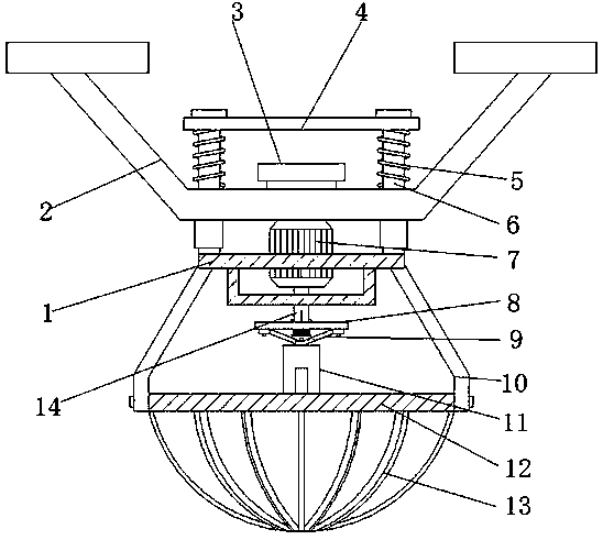
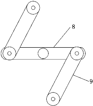
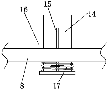
[0018] Embodiment 1, with reference to Figure 1-3 , a UAV grasping device, including a fixed bracket 2, positioning holes are opened on the inner wall of the bottom end of the fixed bracket 2 near the four corners, and positioning rods 6 are inserted into the inner walls of the four positioning holes, and the four The outer wall of the top of the positioning rod 6 is fixed with the same horizontal plate 4 by bolts, and the side walls of the four positioning rods 6 near the bottom of the horizontal plate 4 are sleeved with the first spring member 5, and the bottom ends of the four positioning rods 6 The same installation frame 1 is fixed by bolts, and the outer walls on both sides of the bottom end of the installation frame 1 are welded with support frames 10, and the bottom ends of the outer walls on the opposite side of the two support frames 10 are provided with clamping mechanisms. Circular ring 12, and the two ends of the side walls of the semi-circular ring 12 are flexib...

Embodiment 2

[0020] Embodiment 2, with reference to Figure 1-3 , a UAV grasping device, including a fixed bracket 2, positioning holes are opened on the inner wall of the bottom end of the fixed bracket 2 near the four corners, and positioning rods 6 are inserted into the inner walls of the four positioning holes, and the four The outer wall of the top of the positioning rod 6 is fixed with the same horizontal plate 4 by bolts, and the side walls of the four positioning rods 6 near the bottom of the horizontal plate 4 are sleeved with the first spring member 5, and the bottom ends of the four positioning rods 6 The same installation frame 1 is fixed by bolts, and the outer walls on both sides of the bottom end of the installation frame 1 are welded with support frames 10, and the bottom ends of the outer walls on the opposite side of the two support frames 10 are provided with clamping mechanisms. Circular ring 12, and the two ends of the side walls of the semi-circular ring 12 are flexib...


PUM


Abstract

The invention discloses an unmanned aerial vehicle grabbing device, including a fixing bracket, wherein positioning holes are formed at the positions close to four corners of the inner wall of the bottom end of the fixing bracket; positioning rods are inserted into the inner walls of the four positioning holes; a transverse plate arranged horizontally is fixed on the out walls of the top ends of the four positioning rods by bolts; the positions, close to the bottom end of the transverse plate, of the four positioning rods, are each sleeved with a first spring member; the bottom ends of the four positioning rods are fixed with the same mounting bracket by bolts; the outer walls on both sides of the bottom end of the mounting bracket are welded with support brackets, and clamping mechanismsare arranged at the bottom ends of the outer walls on opposite sides of the two support brackets; and the clamping mechanisms comprise semi-circular rings. The unmanned aerial vehicle grabbing deviceis convenient for grasping the goods, is conducive to improving the grasping success rate, is compact in structure, quick in response, is convenient for grasping and putting the goods, is conducive tolifting the shock absorption performance of the device, is conducive to protecting the goods and enriches the functions of the device.

Description

technical field [0001] The invention relates to the technical field of object-grabbing devices, in particular to an object-grabbing device for an unmanned aerial vehicle. Background technique [0002] Unmanned aircraft, referred to as "unmanned aerial vehicle", or "UAV" in English, is an unmanned aircraft that is controlled by radio remote control equipment and its own program control device, or is completely or intermittently operated autonomously by an on-board computer. Drones are often better suited for missions that are too "dumb, dirty or dangerous" than manned aircraft. According to the application field, UAV can be divided into military and civilian. With the development of drones, drones can be used to carry goods. By installing a grabbing device on the drone, the cargo can be grabbed to improve work efficiency, but the existing grabbing device has a single function and a shock absorption effect. Not good, it is inconvenient to grab the goods, so a UAV grabbing de...

Claims


Application Information

Patent Timeline
Patent Type & Authority Applications(China)
IPC IPC(8): B64D9/00B64D47/00B64C39/02
CPCB64D9/00B64C39/02B64D47/00
Inventor 王涛黄超王翊
Owner 安徽力之航无人机科技有限公司
Why Eureka
Try Eureka