Portable movable clamping mechanism
A clamping mechanism and portable technology, applied in the direction of telephone structure, connecting member, supporting machine, etc., can solve problems such as inconvenience of use, and achieve the effect of convenience for users
- Summary
- Abstract
- Description
- Claims
- Application Information
AI Technical Summary
Problems solved by technology
Method used
Image
Examples
Embodiment 1
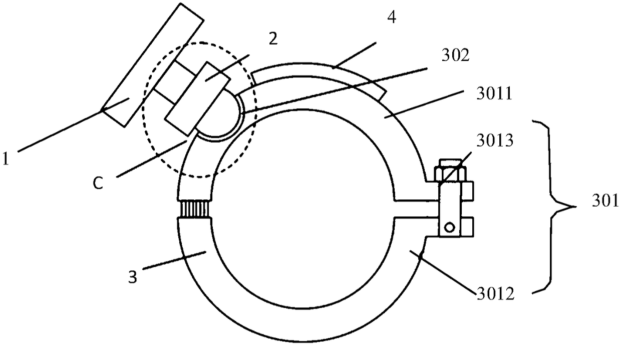
[0054] Such as figure 1 As shown, the present invention provides a portable movable clamping mechanism, which at least includes a support 1 , a movable joint 2 and a base 3 , wherein the support is connected to the base through the movable joint to form a whole. The stand 1 is used for installing an electronic product such as a mobile phone, and the base 3 is used for fixing the stand to a designated place. For example, the portable movable clamping mechanism can be a mobile phone holder, and the support and fixation of the mobile phone can be realized by installing the base on the tubular member so as to be convenient for users to use. The movable link can be respectively connected with the support and the base in a detachable manner. The split design of the support, the movable connector and the support allows each component to be used as a separate functional module to deal with different usage scenarios. For example, the support 1 can be a mobile phone case, and when it ...
Embodiment 2
[0062] This embodiment is a further improvement on Embodiment 1, and repeated content will not be repeated here.
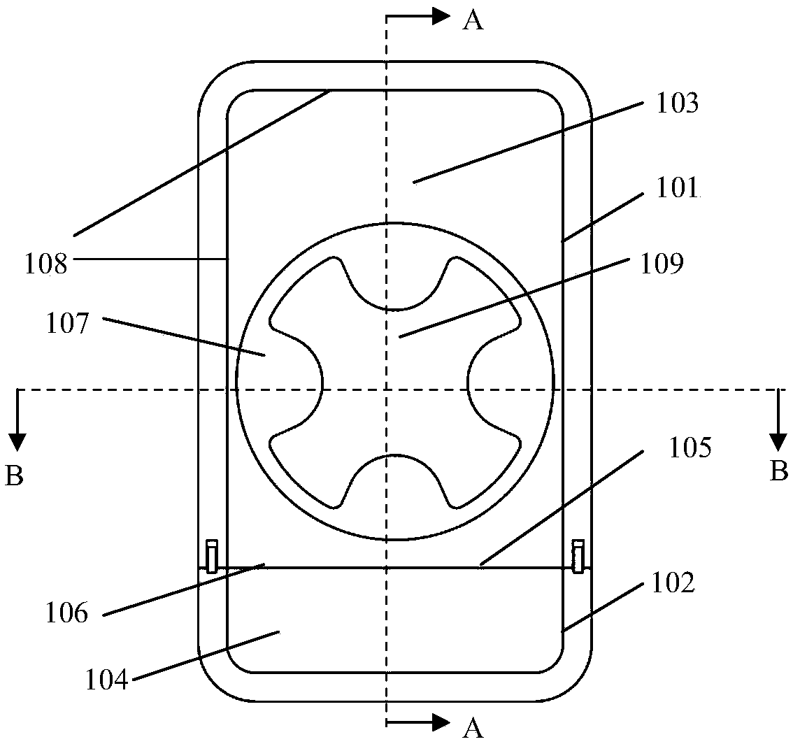
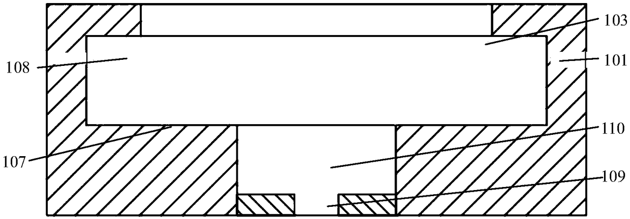
[0063] Such as Figure 7 and Figure 8 As shown, the present invention also provides a movable connecting piece, which is used for movably connecting the support and the bracket in a detachable connection manner. The movable link includes at least a first support body 206 , a first connecting head 207 , a second connecting head 208 and a clamping mechanism 209 . The shape of the first supporting body is defined by a straight line, and the shape of the cross section perpendicular to the axial extension direction thereof may be square or rectangular. In the direction perpendicular to the axial extension of the first support body, the first connection head and the second connection head are fixed on the two surfaces of the first support body in a mirror-symmetrical manner with respect to the first support body, wherein, through the second A connecting head 207 can...
Embodiment 3
[0075] This embodiment is a further improvement on the foregoing embodiments, and repeated content will not be repeated here.
[0076] Such as Figure 14 As shown, preferably, the active connector 2 also includes a central processing unit 305 for data processing, an image collector 306 for collecting image data, a communicator 307 for establishing a communication connection with other electronic products, and a A battery 308 for power supply and an alarm 309 for sound and / or light warning. The activation of the central processing unit, the image collector and the communicator can be triggered based on the connection between the support and the first supporting body. For example, the switches for controlling the opening of the central processing unit, the image acquisition device and the communicator can all be arranged on the clamping plate, and the switch can be closed when the clamping plate and the clamping slot are pressed tightly. Preferably, the image collector, commun...
PUM
 Abstract
Description
Claims
Application Information
 - R&D
- Intellectual Property
- Life Sciences
- Materials
- Tech Scout
- Unparalleled Data Quality
- Higher Quality Content
- 60% Fewer Hallucinations
Browse by: Latest US Patents, China's latest patents, Technical Efficacy Thesaurus, Application Domain, Technology Topic, Popular Technical Reports.
© 2025 PatSnap. All rights reserved.Legal|Privacy policy|Modern Slavery Act Transparency Statement|Sitemap|About US| Contact US: help@patsnap.com


