
Printer

A printer and printing technology, applied in the direction of typewriter, printing, winding strip, etc., can solve the problems of affecting the printing quality and unable to remove the meandering of the ribbon.

Active Publication Date: 2019-01-15
TOSHIBA TEC KK
View PDF11 Cites 0 Cited by
  • Summary
  • Abstract
  • Description
  • Claims
  • Application Information

AI Technical Summary

Problems solved by technology

In addition, due to the above-mentioned cantilever mechanism, if the mounting angles of the tape take-up shaft and the tape holding shaft are slightly different, the tape tends to meander due to deviation from one side.
Moreover, when the ribbon snakes, the printing quality will be affected due to the distortion of the ribbon at the transfer position where the thermal print head abuts against the ribbon.
[0005] As the prior art, although there is disclosed a technique related to a mechanism for adjusting the tension of the ribbon between the take-up shaft and the delivery shaft, the meandering of the ribbon cannot be eliminated.

Method used


Image

  • Printer
  • Printer
  • Printer

Examples


Embodiment Construction

[0041] Hereinafter, the printer according to this embodiment will be described in detail with reference to the drawings. In addition, this invention is not limited by the Example demonstrated below.

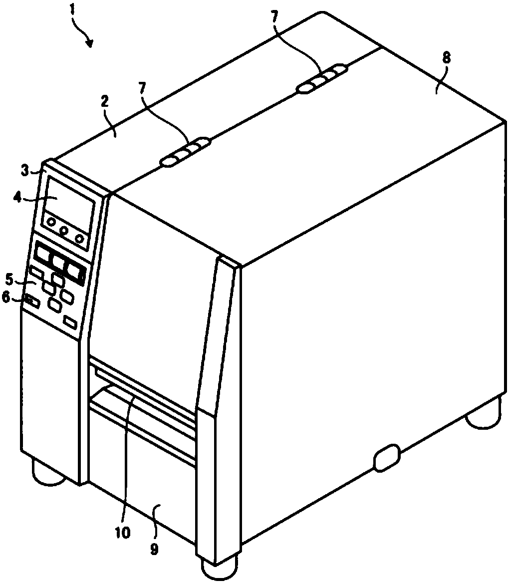
[0042] figure 1 It is an external perspective view of the printer 1 of this embodiment. Such as figure 1 As shown, the printer 1 has a casing 2 on the left side, and a casing 8 connected to the right side of the casing 2 by a hinge 7 . The front panel 3 of the housing 2 has a display unit 4 and an operation unit 5 . The display unit 4 is composed of a liquid crystal display with a backlight, but other types of display devices may also be used. The operation unit 5 has a plurality of operation buttons 6 .

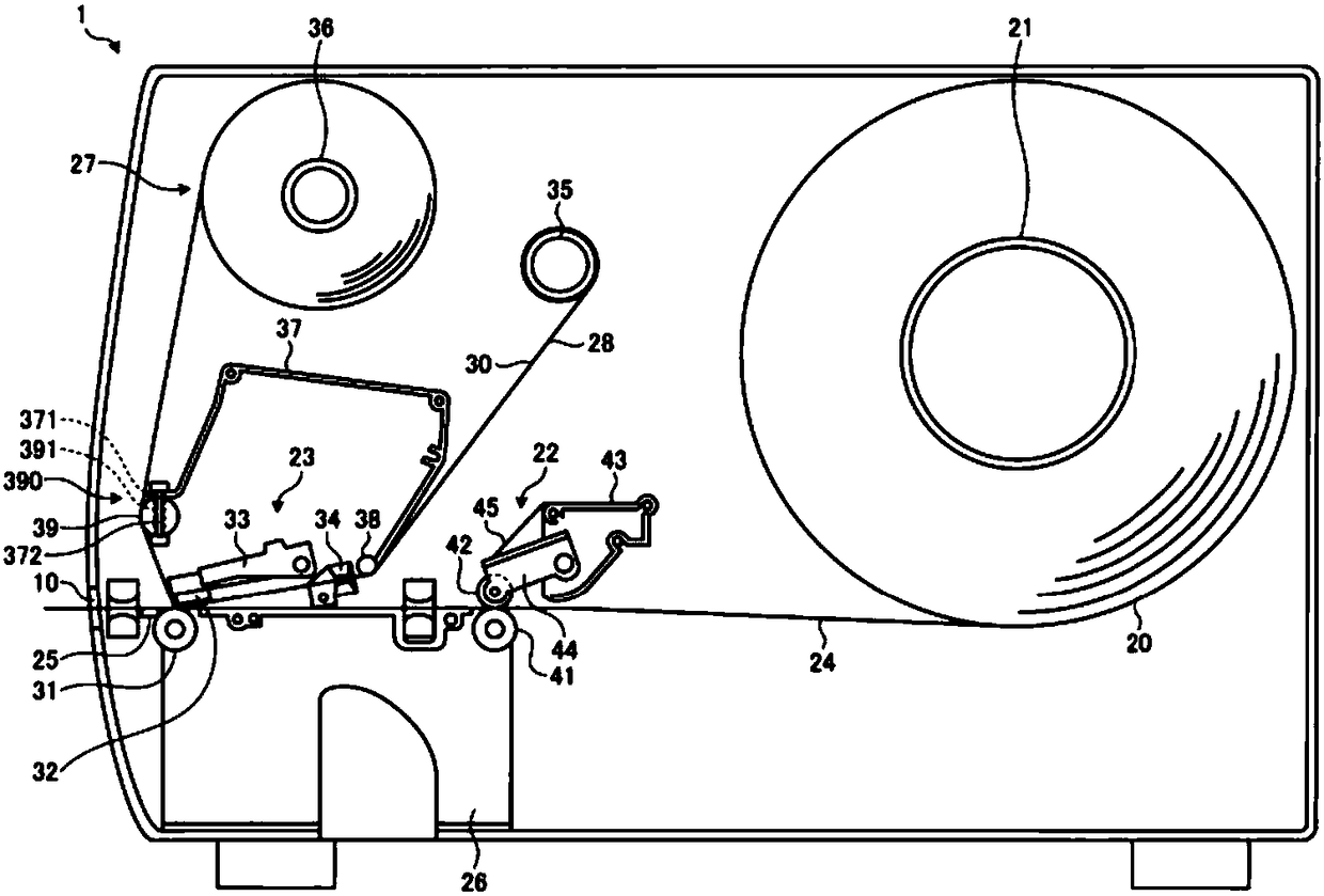
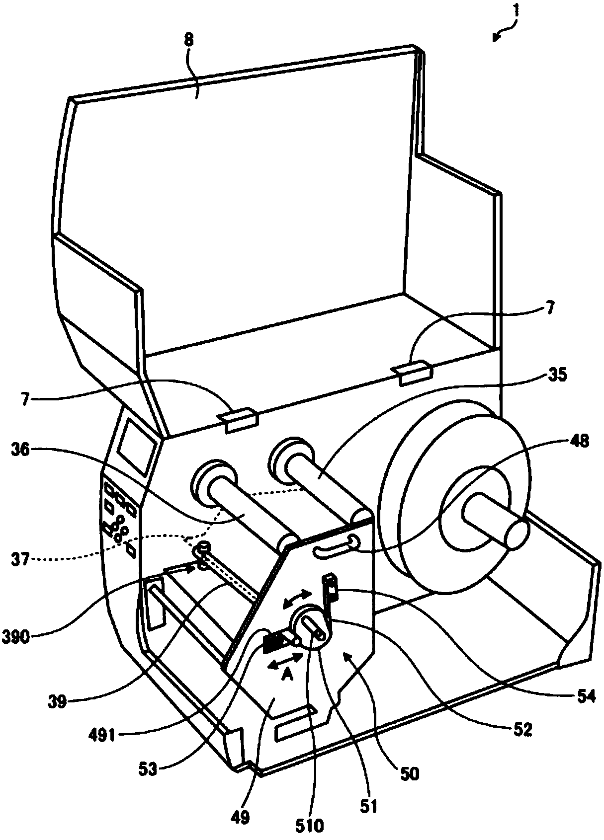
[0043] The housing 8 on the right has a structure in which the inside of the housing (that is, the housings 2 and 8 ) can be largely opened by rotating the hinge 7 . Although with figure 2 While it will be described later, the printer 1 has a label paper 20 wound into a...


PUM


Abstract

The present invention discloses a printer capable of reducing twisting of an ink ribbon. The printer includes a printing unit having a printing head and a platen positioned opposite the printing head,the printing head being configured to print on a print medium that is fed between the printing head and the platen, a ribbon holding shaft configured to hold an ink ribbon before printing that is wound thereon, a ribbon winding shaft configured to wind and collect the ink ribbon after printing, and a pair of guide shafts provided along a feeding route of the ink ribbon between the ribbon holdingshaft and the ribbon winding shaft to erect the ink ribbon, wherein at least one of the pair of guide shafts has a tilt adjuster that changes a tilt of the ink ribbon in a width direction.

Description

[0001] This application claims that the Japanese application with the filing date of July 04, 2017 and the application number of JP2017-131351 is the priority, and cites the content of the above application, and its disclosure content is incorporated herein by reference. technical field [0002] Embodiments of the present invention relate to a printer. Background technique [0003] Currently, in printers such as label printers, a thermal transfer type thermal printer in which ink applied by a thermal printhead is transferred by melting ink applied to a thermal ribbon is widely used. In such a printer, the ink ribbon is stretched over the ribbon holding shaft and the tape take-up shaft, and the ribbon is fed while being rotated by rotating one end of the take-up shaft with a drive motor. That is, the take-up shaft is a cantilever mechanism whose only one end is driven by a drive motor. In addition, in such a printer, there may be a phenomenon that the ink ribbon meanders alo...

Claims


Application Information

Patent Timeline
IPC IPC(8): B41J33/14
CPCB41J33/14B41J35/04B65H23/038B65H2404/15212B41J35/08B41J3/4075B41J2/325
Inventor 浅井良則
Owner TOSHIBA TEC KK
Learn More