A brake pedal simulator, a vehicle braking system and a vehicle

A brake pedal and simulator technology, applied in the direction of brakes, foot start devices, etc., can solve the problems of low operation, large fluctuation of simulated pedal force, and complex structure, etc.

Active Publication Date: 2019-01-15
BYD CO LTD
View PDF7 Cites 0 Cited by
  • Summary
  • Abstract
  • Description
  • Claims
  • Application Information

AI Technical Summary

Problems solved by technology

The pedal simulator using this hydraulic control method is not only complex in structure, but also has the problem of low op

Method used


Image

  • A brake pedal simulator, a vehicle braking system and a vehicle
  • A brake pedal simulator, a vehicle braking system and a vehicle
  • A brake pedal simulator, a vehicle braking system and a vehicle

Examples


Embodiment Construction

[0047] The specific embodiments of the present disclosure will be described in detail below with reference to the accompanying drawings. It should be understood that the specific embodiments described herein are only used to illustrate and explain the present disclosure, but not to limit the present disclosure.

[0048] In the present disclosure, where not stated to the contrary, the use of directional words such as "inside, outside" generally refers to the inside and outside of the contour of the corresponding component.

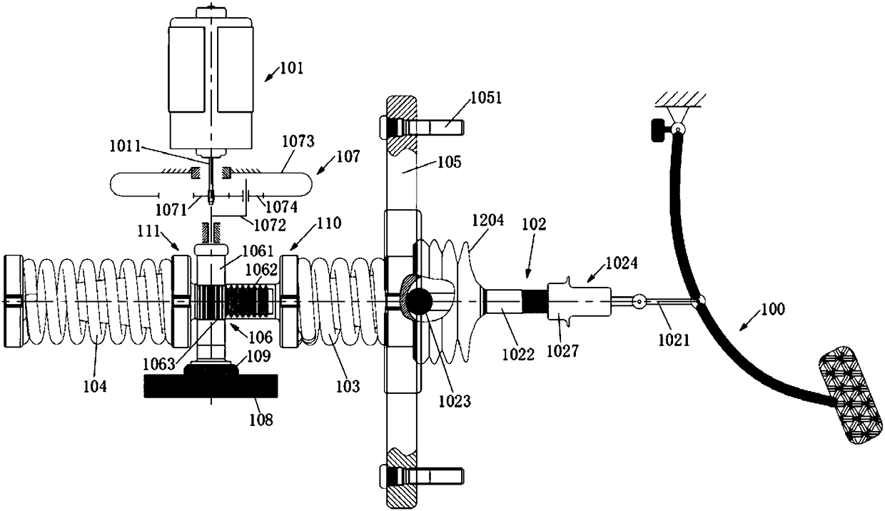
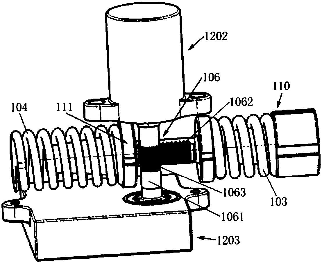
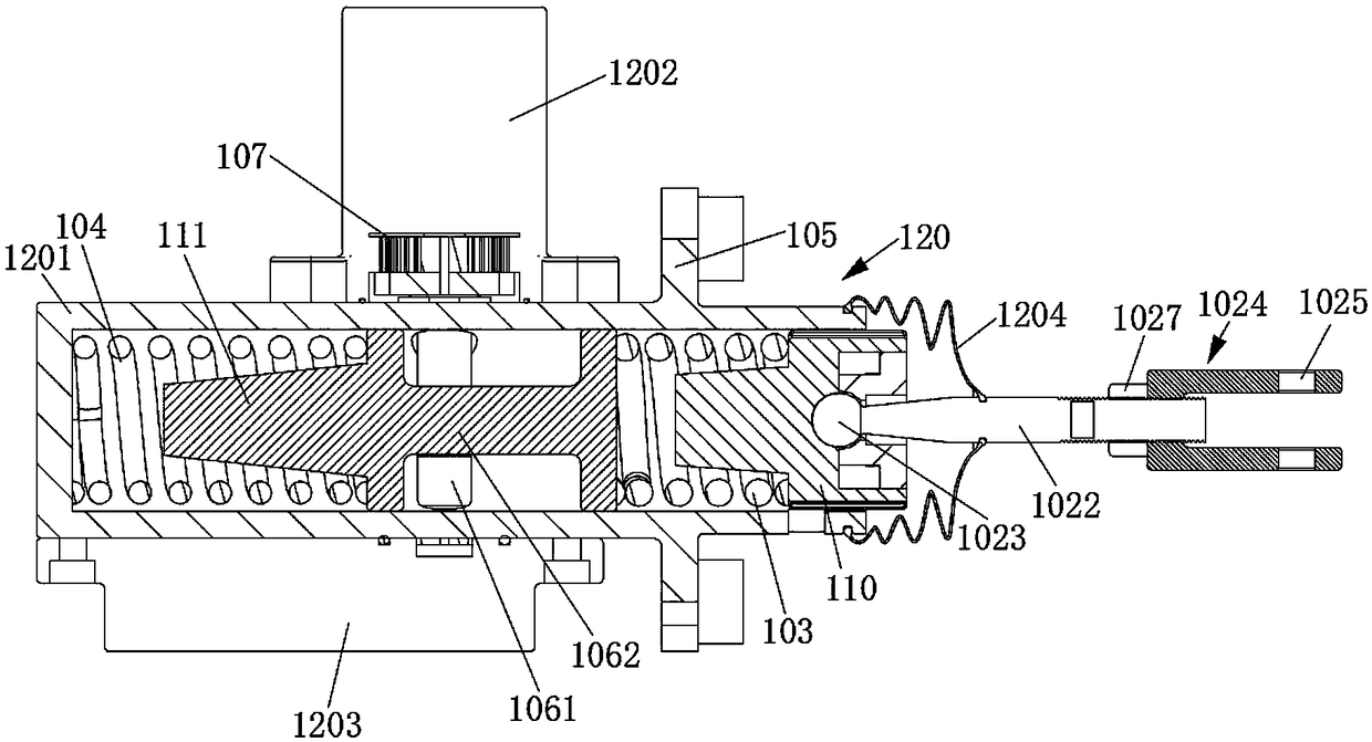
[0049] The present disclosure provides a brake pedal simulator, a vehicle braking system, and a technical solution for a vehicle. The brake pedal simulator of the present disclosure simulates the characteristics of the brake pedal by using an elastic element and a braking method. Here, the characteristics of the brake pedal are usually represented by the corresponding relationship between the pedal force, the pedal stroke and the braking response time. . ...


PUM


Abstract

A brake pedal simulator, a vehicle braking system and a vehicle are provided, wherein the brake pedal simulator includes a brake pedal, a booster motor, an assembly part for fitting to a vehicle body,a first elastic member and a second elastic member arranged at axially spaced intervals on both sides of the fitting portion, a rack and pinion mechanism located between the first elastic member andthe second elastic member, and a thrust structure hinged to the brake pedal and cooperating with the first elastic member to drive the first elastic member and the second elastic member while telescoping in the axial direction. The first elastic member and the second elastic member cooperate together to provide a pedal preset force to the brake pedal, and the output shaft of the booster motor cooperates with the first elastic member and the second elastic member through a rack and pinion mechanism to be able to provide a driving force for the thrust structure. This provides a reliable brakingfeel of the brake pedal and simulates an accurate brake pedal force, and has the effects of good operation stability and corresponding quick brake pedal.

Description

technical field [0001] The present disclosure relates to the technical field of vehicle braking systems, and in particular, to a brake pedal simulator, a vehicle braking system and a vehicle. Background technique [0002] In existing vehicles, especially in electric vehicles, part of the braking system cancels the hydraulic or mechanical connection between the brake pedal and the brake of the traditional braking system, so that the driver cannot directly perceive the feedback to the brake pedal when braking. Braking reaction force, thereby losing the braking feel of traditional braking systems. Among them, the braking feeling refers to the comprehensive feeling of many factors including the pedal braking feeling, the vehicle braking deceleration felt by the driver, the audible braking noise, and the visual vehicle deceleration, among which, the pedal braking feeling for the most important part. For the above-mentioned braking system, a brake pedal simulator is usually adde...

Claims


Application Information

Patent Timeline
IPC IPC(8): B60T8/40B60T7/06
CPCB60T7/06B60T8/409
Inventor 李传博王铁君刘苏丽郑祖雄
Owner BYD CO LTD
Why Eureka
Try Eureka