A high-definition aerial photography optical lens and bracket
An optical lens and lens technology, applied in the direction of optics, optical components, instruments, etc., can solve the problems of inability to adjust the angle, speed up work efficiency, and small degree of freedom of the lens, and achieve the effects of convenient installation, increased stability, and reduced flight distance
- Summary
- Abstract
- Description
- Claims
- Application Information
AI Technical Summary
Problems solved by technology
Method used
Image

Examples
Embodiment 1
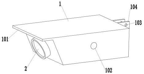
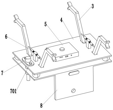
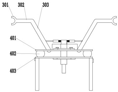
[0031] Such as Figure 1-8 As shown, a high-definition aerial photography optical lens and bracket, the optical lens is matched with the bracket, the optical lens includes a housing 1, the front end of the housing 1 is an inclined surface, and a lens column 2 is provided on the inclined surface, The support includes a gripper 3, a carrier 4, a controller 5, a fixing device 6, and an electric push rod 7. The upper end of the carrier 4 is provided with a gripper 3, and the number of the grippers 3 is four, and the gripper 3. Left and right symmetrical, a fixing device 6 is provided between the grippers 3, the fixing device 6 is connected to the carrier 4, the controller 5 is arranged in the middle of the upper end of the carrier 4, and the electric push rod 7 is arranged on the carrier 4 On one side, the electric push rod 7 is vertically connected with the carrier 4 through the fixing plate 701, and both sides of the lower end of the carrier 4 are provided with mounting connecti...
Embodiment 2
[0033] Such as Figure 1-8 As shown, a high-definition aerial photography optical lens and bracket, the optical lens is matched with the bracket, the optical lens includes a housing 1, the front end of the housing 1 is an inclined surface, and a lens column 2 is provided on the inclined surface, The support includes a gripper 3, a carrier 4, a controller 5, a fixing device 6, and an electric push rod 7. The upper end of the carrier 4 is provided with a gripper 3, and the number of the grippers 3 is four, and the gripper 3. Left and right symmetrical, a fixing device 6 is provided between the grippers 3, the fixing device 6 is connected to the carrier 4, the controller 5 is arranged in the middle of the upper end of the carrier 4, and the electric push rod 7 is arranged on the carrier 4 On one side, the electric push rod 7 is vertically connected with the carrier 4 through the fixing plate 701, and both sides of the lower end of the carrier 4 are provided with mounting connecti...
Embodiment 3
[0036] Such as Figure 1-8 As shown, a high-definition aerial photography optical lens and bracket, the optical lens is matched with the bracket, the optical lens includes a housing 1, the front end of the housing 1 is an inclined surface, and a lens column 2 is provided on the inclined surface, The support includes a gripper 3, a carrier 4, a controller 5, a fixing device 6, and an electric push rod 7. The upper end of the carrier 4 is provided with a gripper 3, and the number of the grippers 3 is four, and the gripper 3. Left and right symmetrical, a fixing device 6 is provided between the grippers 3, the fixing device 6 is connected to the carrier 4, the controller 5 is arranged in the middle of the upper end of the carrier 4, and the electric push rod 7 is arranged on the carrier 4 On one side, the electric push rod 7 is vertically connected with the carrier 4 through the fixing plate 701, and both sides of the lower end of the carrier 4 are provided with mounting connecti...
PUM
 Abstract
Description
Claims
Application Information
 - R&D
- Intellectual Property
- Life Sciences
- Materials
- Tech Scout
- Unparalleled Data Quality
- Higher Quality Content
- 60% Fewer Hallucinations
Browse by: Latest US Patents, China's latest patents, Technical Efficacy Thesaurus, Application Domain, Technology Topic, Popular Technical Reports.
© 2025 PatSnap. All rights reserved.Legal|Privacy policy|Modern Slavery Act Transparency Statement|Sitemap|About US| Contact US: help@patsnap.com