Multi-unmanned aerial vehicle path planning method

A path planning and multi-UAV technology, applied in the field of UAVs, can solve the problems of inability to obtain flight time path planning results, difficult task assignment results, and low algorithm efficiency

Active Publication Date: 2021-04-09
XIDIAN UNIV +1
View PDF9 Cites 3 Cited by
  • Summary
  • Abstract
  • Description
  • Claims
  • Application Information

AI Technical Summary

Problems solved by technology

However, this method uses the branch and bound method to allocate tasks. Since the efficiency of the branch and bound method is basically determined by the value bound method when solving the problem, it is difficult to estimate the bound wh

Method used


Image

  • Multi-unmanned aerial vehicle path planning method
  • Multi-unmanned aerial vehicle path planning method
  • Multi-unmanned aerial vehicle path planning method

Examples


Embodiment Construction

[0041] The present invention will be described in further detail below in conjunction with the accompanying drawings and specific embodiments.

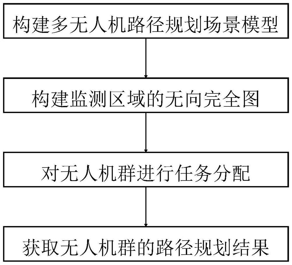
[0042] refer to figure 1 , the present invention comprises the following steps:

[0043] Step 1) Construct multi-UAV path planning scene model:

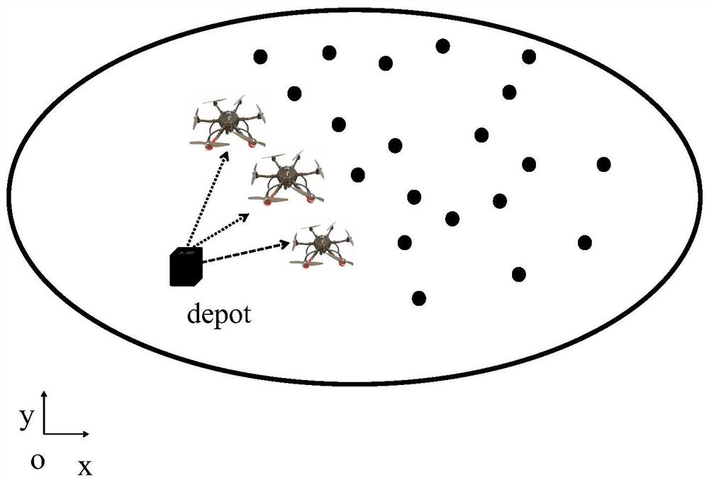
[0044] Construction includes the monitoring area distributed in the three-dimensional rectangular coordinate system xoy plane and the drone group A={A in the space of the three-dimensional rectangular coordinate system i |1≤i≤M} multi-UAV path planning scene model, its structure is as follows figure 2 As shown, the monitoring area includes the starting point depot of UAV A and N monitoring points V={n j |1≤j≤N}, where M represents the number of drones, M≥2, A i Indicates the flight altitude is H i The i-th UAV, n j Indicates that the position coordinates are (x j ,y j ), N≥M, M=3, N=20 in this embodiment.

[0045] Step 2) Construct an undirected complete graph of the monitoring are...


PUM


Abstract

The invention provides a multi-unmanned aerial vehicle path planning method. The method comprises the following steps: constructing a multi-unmanned aerial vehicle path planning scene model; constructing an undirected complete graph of the monitoring area; carrying out the task allocation on the unmanned aerial vehicle group; and obtaining a path planning result of the unmanned aerial vehicle group. An undirected complete graph of a monitoring area is constructed, a monitoring point traversed by each unmanned aerial vehicle and a starting point are modeled into the undirected complete graph, point transfer and exchange operations are carried out between the undirected complete graphs to continuously optimize a task allocation result, and a minimum Hamiltonian ring of each unmanned aerial vehicle is obtained on the basis of the optimized task allocation result; point transfer is carried out between the minimum Hamiltonian rings, the task allocation result is further optimized, and the path planning result of the unmanned aerial vehicle group is obtained, so the flight distance of the unmanned aerial vehicle with the maximum flight distance in the multiple unmanned aerial vehicles is minimum, and the flight time is the shortest.

Description

technical field [0001] The invention belongs to the technical field of unmanned aerial vehicles, and relates to a multi-unmanned aerial vehicle path planning method. Background technique [0002] Due to its high mobility, flexible deployment, and low cost, unmanned aerial vehicle (UAV) has attracted more and more attention from academia and industry. For example, UAV can be used in various scenarios such as smart farms, search and rescue, and post-disaster assessment. self-monitoring. Due to the lack of real-time, completeness, and reliability of a single UAV in performing tasks, multiple UAVs are required to perform tasks. When conducting research on the problems caused by multi-UAV missions, The coupling of tasks makes the coordination problem arise at the historic moment. The key technical challenge to solve the multi-UAV coordination problem is how to plan an efficient flight path for each UAV under the premise of ensuring that all tasks are completed; The solution ste...

Claims


Application Information

Patent Timeline
IPC IPC(8): G01C21/20
CPCG01C21/20
Inventor 张琰刘佳玥焦利彬索宏泽岳群彬聂冬冬魏艺璇朱继坡刘杰
Owner XIDIAN UNIV
Why Eureka
Try Eureka