

Micro LED array device, mass transfer device and related method
An array and device technology, which is applied in the field of mass transfer devices and Micro LED array devices, can solve the problems of poor light utilization and light consumption, and achieve the effects of improving efficiency, simplifying transfer methods, and avoiding manufacturing and removal processes
- Summary
- Abstract
- Description
- Claims
- Application Information
AI Technical Summary
Problems solved by technology
Method used
Image

Examples
Embodiment Construction
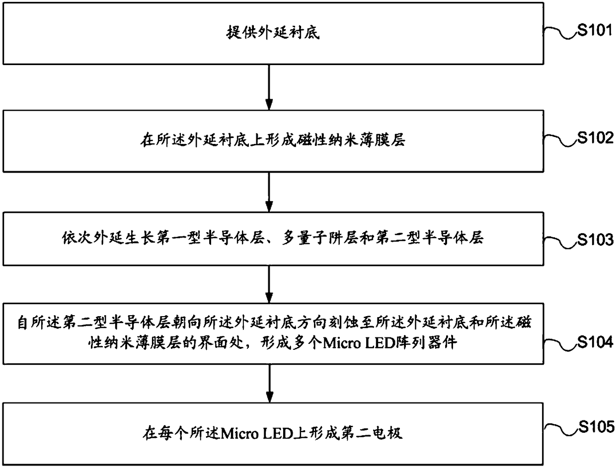
[0053]As mentioned in the background technology section, one of the difficulties in the development of Micro LED technology currently lies in the mass transfer process of Micro LED.
[0054] The inventors found that, in the prior art, methods such as bonding are provided for mass transfer, but the bonding method requires the setting of an adhesive layer and subsequent removal, which makes the process of mass transfer less efficient. Or in the prior art, a magnetic layer is added to the external structure of the light-emitting diode, and the structure is adsorbed by magnetic force. However, since an adhesive layer is required to adhere multiple Micro LED array devices together, the adhesion needs to be removed later. The attached layer and the additional magnetic layer make the operation complicated and many steps in the mass transfer process of Micro LED array devices.
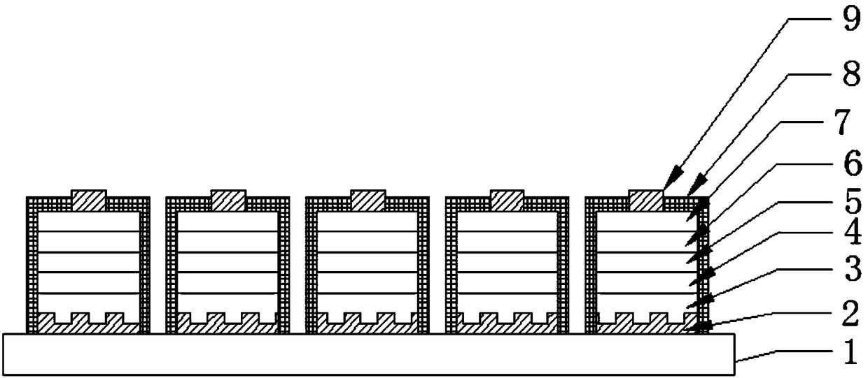
[0055] Based on this, the present invention provides a Micro LED array device, including:
[0056] A Micro...
PUM
| Property | Measurement | Unit |
|---|---|---|
| Thickness range | aaaaa | aaaaa |
Abstract
Description
Claims
Application Information