Over-current detection circuit
An overcurrent detection and circuit technology, applied in the direction of measuring electrical variables, measuring current/voltage, measuring devices, etc., can solve the problem that the blanking time is difficult to cover, the conduction delay and transmission delay of the power switch tube are not a stable value, susceptibility to other factors, etc.
- Summary
- Abstract
- Description
- Claims
- Application Information
AI Technical Summary
Problems solved by technology
Method used
Image

Examples
Embodiment 1
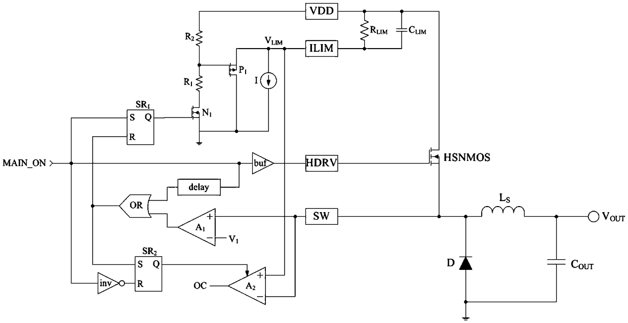
[0027] The present invention provides an over-current detection circuit used in high-speed switching converters, the structure of the over-current detection circuit is as follows figure 1 As shown, it includes a ringing compensation circuit and an overcurrent detection comparator; the ringing compensation circuit is used to avoid the false triggering of the overcurrent protection caused by the ringing voltage of the switching node of the power tube, and the overcurrent detection comparator , which is used to compare the operating current of the power tube with the current-limiting threshold and generate an over-current protection signal.
[0028] Specifically, please continue to figure 1 . The ringing compensation circuit includes a main turn-on signal MAIN_ON, and simultaneously accesses the buffer buf, the delay unit delay, the inverter inv and the first SR flip-flop SR 1 and the buffer buf is connected to the HDRV pin; the output of the delay unit delay is connected to th...
PUM
 Abstract
Description
Claims
Application Information
 - R&D
- Intellectual Property
- Life Sciences
- Materials
- Tech Scout
- Unparalleled Data Quality
- Higher Quality Content
- 60% Fewer Hallucinations
Browse by: Latest US Patents, China's latest patents, Technical Efficacy Thesaurus, Application Domain, Technology Topic, Popular Technical Reports.
© 2025 PatSnap. All rights reserved.Legal|Privacy policy|Modern Slavery Act Transparency Statement|Sitemap|About US| Contact US: help@patsnap.com