Supercharge Your Innovation With Domain-Expert AI Agents!

Liquid crystal display panel driving circuit and driving method

A liquid crystal display panel and driving circuit technology, applied in static indicators, instruments, etc., can solve the problems of liquid crystal display panel burnout, excessive clock signal wiring current, short circuit, etc., and achieve the effect of avoiding false triggering of overcurrent protection

Active Publication Date: 2020-05-29
TCL CHINA STAR OPTOELECTRONICS TECH CO LTD
View PDF6 Cites 0 Cited by
  • Summary
  • Abstract
  • Description
  • Claims
  • Application Information

AI Technical Summary

Problems solved by technology

Due to the many clock signal traces inside the GOA, short circuits are prone to occur due to the manufacturing process. In order to prevent the LCD panel from being burned out, a structure with an over-current protection (OCP) function will be provided for the clock signal traces. However, for Eliminate brightness unevenness (mura). In the prior art, the timing controller will stop outputting the initial clock signal in a short time to reset the clock signal. Since the time to stop outputting the initial clock signal is short, the liquid crystal The display panel cannot be fully discharged. At this time, the timing controller outputs the initial clock signal again, which will cause the current on the clock signal line to be too large and trigger the over-current protection. However, there is no short circuit between the clock signal lines at this time, that is, False triggering of overcurrent protection

Method used


Image

  • Liquid crystal display panel driving circuit and driving method
  • Liquid crystal display panel driving circuit and driving method
  • Liquid crystal display panel driving circuit and driving method

Examples


Embodiment Construction

[0043] In order to further illustrate the technical means adopted by the present invention and its effects, the following describes in detail in conjunction with preferred embodiments of the present invention and accompanying drawings.

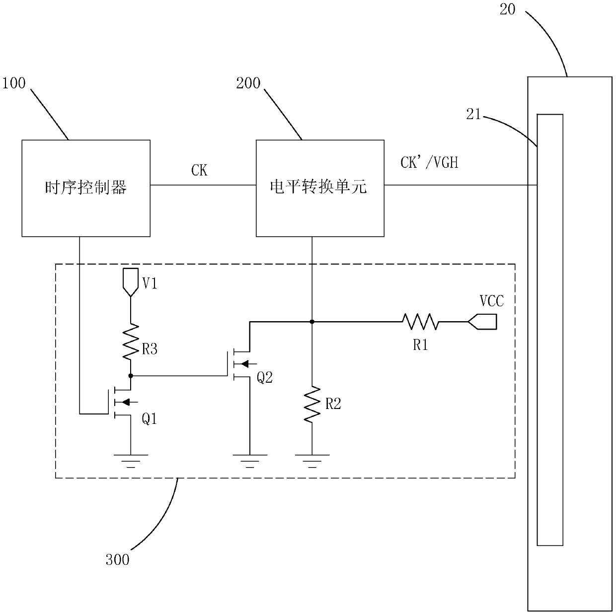
[0044] see figure 1 , the present invention provides a liquid crystal display panel driving circuit, including a timing controller 100, a level conversion unit 200 electrically connected to the timing controller 100, and a timing controller 100 and a level conversion unit 200 both an electrically connected control signal generating unit 300;

[0045] Wherein, the working mode of the liquid crystal display panel driving circuit includes a driving mode and a reset mode;

[0046] In the reset mode, the timing controller 100 outputs a reset signal to the control signal generating unit 300, and the control signal generating unit 300 receives the reset signal and generates a corresponding control signal and outputs it to the level conversion unit 2...


PUM


Abstract

The invention provides a liquid crystal display panel drive circuit and a liquid crystal display drive method. The liquid crystal display panel drive circuit comprises a timing sequence controller, a level switching unit and a control signal generating unit. The work mode of the liquid crystal display panel drive circuit comprises a reset mode, in the reset mode, the timing sequence controller outputs a reset signal to the control signal generating unit, the control signal generating unit receives the reset signal, generates a corresponding control signal and outputs the control signal to the level switching unit, the level switching unit is controlled by the control signal to output a constant-voltage high potential to a GOA circuit of a liquid crystal panel so that the liquid crystal display panel can be quickly discharged in the reset mode, and the situation that after the liquid crystal display panel drive circuit enters a drive mode again, the current on a clock signal wire is over high, and over-current protection is triggered is avoided.

Description

technical field [0001] The invention relates to the technical field of liquid crystal display, in particular to a driving circuit and a driving method of a liquid crystal display panel. Background technique [0002] With the development of display technology, liquid crystal display (Liquid Crystal Display, LCD) and other flat display devices are widely used in mobile phones, TVs, Various consumer electronic products such as personal digital assistants, digital cameras, notebook computers, and desktop computers have become the mainstream of display devices. [0003] In an active liquid crystal display device, each pixel is electrically connected to a thin film transistor (TFT), the gate (Gate) of the thin film transistor is connected to the horizontal scanning line, the source (Source) is connected to the vertical data line, and the drain ( Drain) is connected to the pixel electrode. Applying sufficient voltage on the horizontal scanning line will turn on all the TFTs elect...

Claims


Application Information

Patent Timeline
Patent Type & Authority Patents(China)
IPC IPC(8): G09G3/36
CPCG09G3/3648
Inventor 李文芳张先明
Owner TCL CHINA STAR OPTOELECTRONICS TECH CO LTD
Features
  • R&D
  • Intellectual Property
  • Life Sciences
  • Materials
  • Tech Scout
  • Unparalleled Data Quality
  • Higher Quality Content
  • 60% Fewer Hallucinations
Learn More