Supercharge Your Innovation With Domain-Expert AI Agents!

Power source device, power source system and power supply method

A power supply device and power system technology, applied in the electronic field, can solve problems such as false triggering of overcurrent protection by electronic equipment, excessive circuit current, etc.

Inactive Publication Date: 2015-11-11
INSPUR GROUP CO LTD
View PDF6 Cites 2 Cited by
  • Summary
  • Abstract
  • Description
  • Claims
  • Application Information

AI Technical Summary

Problems solved by technology

At present, the power module is directly added mainly through hot-swapping. When a new power module is inserted, the power module will generate a large instantaneous current, and when the large instantaneous current flows directly to the electronic equipment, it may cause some The circuit current is too large, causing the electronic equipment to trigger the over-current protection by mistake

Method used


Image

  • Power source device, power source system and power supply method
  • Power source device, power source system and power supply method
  • Power source device, power source system and power supply method

Examples


specific Embodiment approach

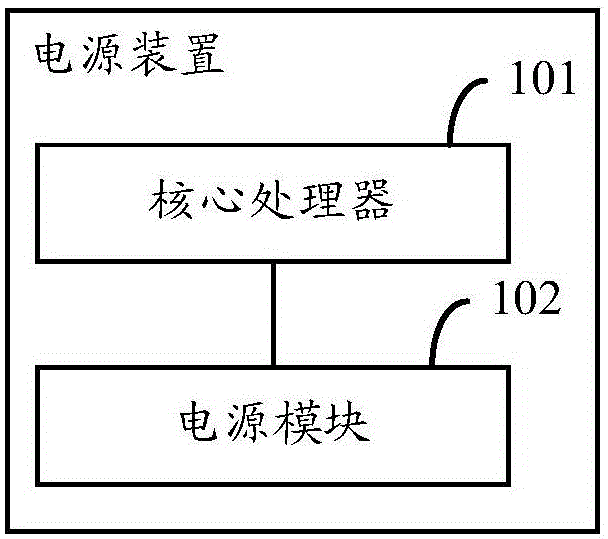
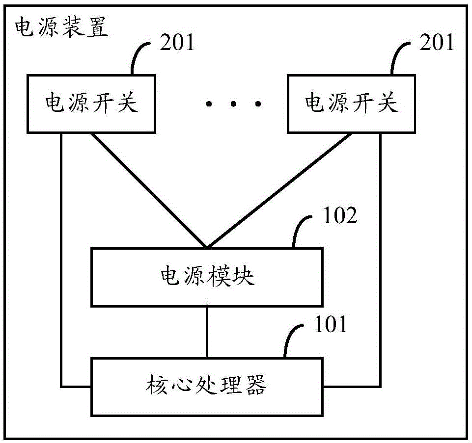
[0061] In one embodiment of the present invention, in order to more conveniently and simply control the power supply for the specified power load module, the power supply method further includes: setting at least one power switch in the power supply device described in step 401; Specific implementation method: connect the power supply module with at least one peripheral power supply load module through at least one power switch, wherein each power switch has a one-to-one correspondence with at least one peripheral power supply load module; the specific implementation manner of step 403 : After the core processor determines any one or more power load modules of peripherals that need to increase power, by closing the power switch corresponding to the power load modules of any one or more peripherals, the power module is realized as Any one or more power supply load modules in the at least one power supply load module supply power; after the core processor determines that any one ...


PUM


Abstract

The invention provides a power source device, a power source system and a power supply method. The power source device comprises a core processor and a power source module, wherein the core processor is connected with the power source module, and the power source module is used for obtaining electric quantity from an external power supply circuit, and is connected with at least one external power source load module under the control the core processor, and supplies power for any one or a plurality of external power source load modules in the at least one external power source load module. When the power source device is connected with a power source bottom plate in a hot plug manner, an electric device can be effectively prevented from wrongly triggering over-current protection.

Description

technical field [0001] The invention relates to the field of electronic technology, in particular to a power supply device, a power supply system and a power supply method. Background technique [0002] In various electronic devices, such as televisions, computers, servers, etc., the power module usually needs to obtain 220V AC power from the outside, and convert the 220V AC power into a small voltage that can be loaded by each module in the electronic device, such as 12V, 8V and 5V, etc. Direct current, so that the various modules in the electronic equipment can operate normally. [0003] As the functions of electronic equipment become more and more powerful, the power required for normal operation of electronic equipment is also increasing. Then, when the existing power module cannot meet the operation of electronic equipment, it is necessary to increase the power module to ensure the normal operation of electronic equipment. At present, the power module is directly added...

Claims


Application Information

Patent Timeline
IPC IPC(8): H02M1/00H02M7/02
Inventor 冉宇峰梁华勇肖时航
Owner INSPUR GROUP CO LTD
Features
  • R&D
  • Intellectual Property
  • Life Sciences
  • Materials
  • Tech Scout
  • Unparalleled Data Quality
  • Higher Quality Content
  • 60% Fewer Hallucinations
Learn More