Trickle discharge for battery pack protection

A technology of trickle discharge and battery pack, which is applied in the direction of secondary battery charging/discharging, battery circuit device, emergency protection circuit device, etc., and can solve the problem of damaging the battery pack, etc.

Active Publication Date: 2008-05-14
O2MICRO CHINA
View PDF0 Cites 11 Cited by
  • Summary
  • Abstract
  • Description
  • Claims
  • Application Information

AI Technical Summary

Problems solved by technology

However, if the abnormal condition exists for a long period of time, a large current will continuously flow through the discharge FET 18, which will eventually destroy the battery pack 22 and / or the MOSFET

Method used


Image

  • Trickle discharge for battery pack protection
  • Trickle discharge for battery pack protection
  • Trickle discharge for battery pack protection

Examples


Embodiment Construction

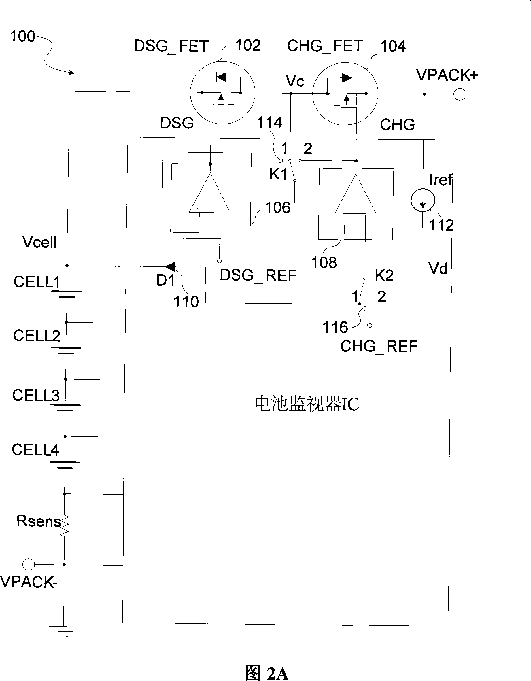
[0026] FIG. 2A shows a typical trickle precharge circuit 100 according to the present invention. In this embodiment, two MOSFETs 104 and 102 are used (charge FET CHG_FET and discharge FET DSG_FET). In this embodiment, charge FET 104 and discharge FET 102 are placed back-to-back in series in the manner described. In trickle precharge mode, the discharge FET 102 is off (non-conductive), but if the charge FET (CHG_FET) 104 is on (conductive), current still flows through its body diode to the battery cell. If CHG_FET 104 is off, no current flows into or out of the battery cell.

[0027] Besides the two MOSFETs, the circuit 100 may also include a reference diode D1110 , a discharge driver 106 , a charge driver 108 , and a reference current source Iref112 . Charge driver 108 and discharge driver 106 each include respective comparators. In normal charging mode, switches K1 and K2 (114 and 116) are set to position 2. In this position, the charge drive voltage CHG is driven to the ...


PUM


Abstract

Battery protection circuitry and method are disclosed. A battery is protected from a large current overdrawn condition by setting a discharge switch into a controllable conduction state. After the discharge switch is in the controllable conduction state, a tickle discharge current is gradually generated under control of a control signal. The trickle discharge current can be used to determine whether the large current overdrawn condition still exists. When the large current overdrawn condition is removed, the discharge switch is turned back on.

Description

technical field [0001] The invention relates to a battery charging / discharging circuit and battery group protection, in particular to a battery charging / discharging circuit capable of trickle precharging and / or trickle discharging. The utility of the present invention may be found in charge / discharge / protection systems for use in portable electronic devices, eg, laptop computers, PDAs, cell phones, and / or any type of electronic device with rechargeable batteries. Background technique [0002] Rechargeable batteries, especially Li-ion batteries, require a trickle precharge (recovery charge) from a depleted state to avoid damage to a depleted battery. When the rechargeable battery is drained and its battery voltage becomes lower than the threshold voltage V UV , cannot use a large charging current for direct charging. Instead, a precharge mode is required. In precharge mode, use a small charging current until the battery voltage is charged to a voltage greater than V UV , ...

Claims


Application Information

Patent Timeline
Patent Type & Authority Applications(China)
IPC IPC(8): H02J7/00H01M10/44H02H7/18
CPCY02E60/12Y02E60/10
Inventor 刘柳胜布鲁斯·丹宁
Owner O2MICRO CHINA
Why Eureka
Try Eureka