Hot melting apparatus

A hot-melt device and hot-melt technology, applied in the field of hot-melt, can solve problems such as no tight connection at the joint, affecting work efficiency, and broken joints, so as to prevent air bubbles and achieve good results

Pending Publication Date: 2019-01-22
YINGSHANG BOHAO PLASTIC IND TECH CO LTD
View PDF0 Cites 0 Cited by
  • Summary
  • Abstract
  • Description
  • Claims
  • Application Information

AI Technical Summary

Problems solved by technology

[0004] The purpose of the present invention is to provide a hot-melt device to solve the problem that the joints of the just hot-melt-connected PVC boards proposed in the above background technology are not tightly connected, so when they are removed, it is easy to cause the joints to break and affect the work. efficiency problem

Method used


Image

  • Hot melting apparatus
  • Hot melting apparatus

Examples


Embodiment 1

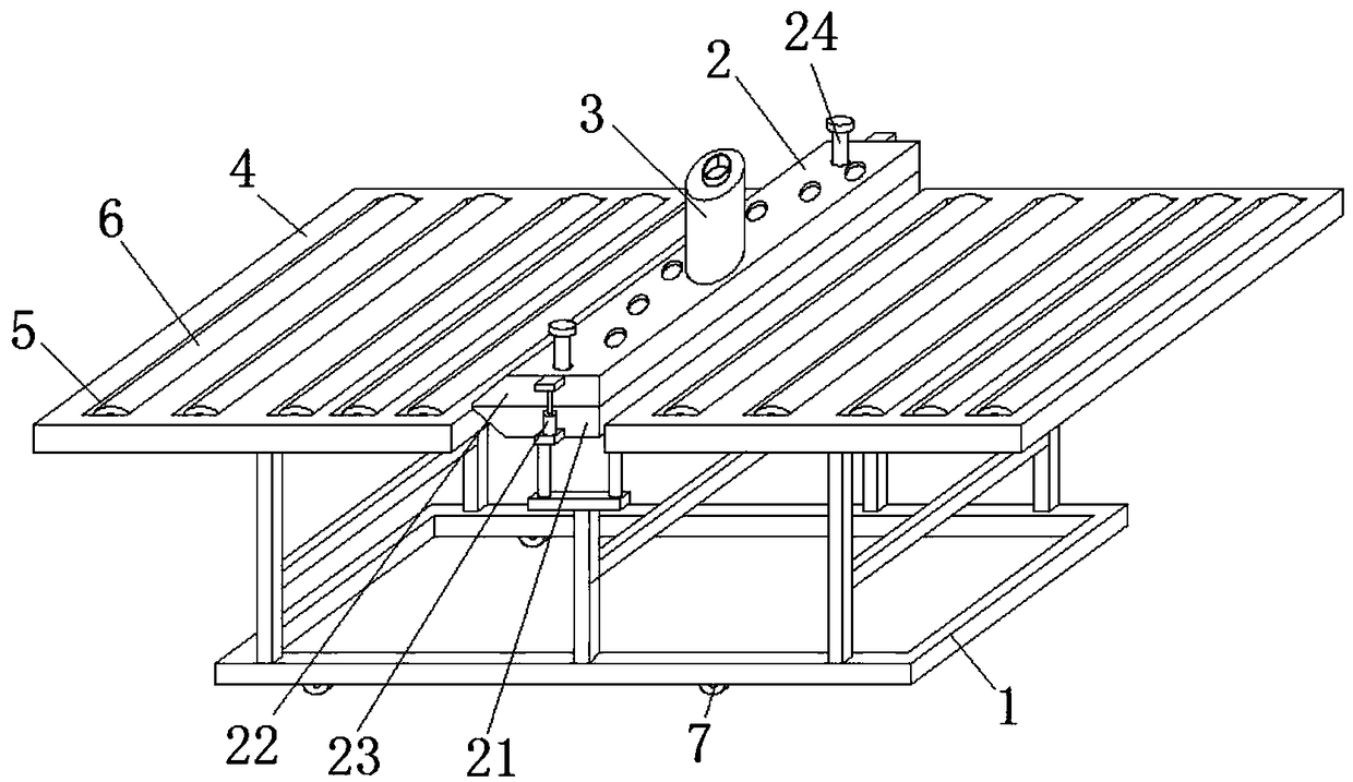
[0018] see Figure 1-2 , this embodiment provides a hot-melt device, including a frame 1, a hot-melt part 2 is fixedly installed on the top of the frame 1, and a feeding device 3 is arranged on the top of the hot-melt part 2, and the through-heating device 3 of the feeding device 3 The melting part 2 extends to the inside of the hot melting part 2. The top of the frame 1 is fixedly connected with the transfer table 4 located on both sides of the hot melting part 2. The top of the transfer table 4 is provided with a mounting groove 5, and the inner wall of the mounting groove 5 is rotatably connected with Transmission wheel6.

[0019] In this embodiment, the plates at both ends are connected by the hot-melt part 2, and the connected PVC plate is moved on the transfer platform 4 by the transmission wheel 6, so that it always moves in a horizontal state, avoiding the Turn up the PVC sheet to prevent the breakage of the connection, and set the transfer table 4 on both sides of th...

Embodiment 2

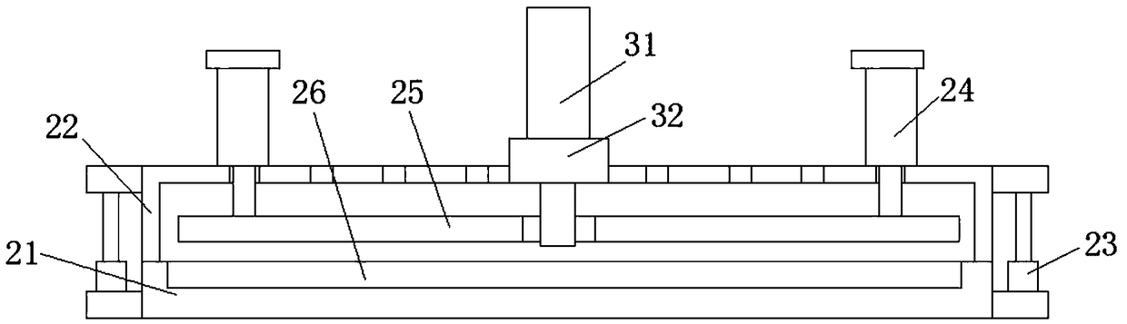
[0021] see Figure 1-2 , On the basis of Embodiment 1, a further improvement is made: the hot-melt part 2 includes a lower cold mold 21 and an upper cold mold 22, a hydraulic cylinder 23 is arranged between the lower cold mold 21 and the upper cold mold 22, and the upper cold mold 22 The top of the cylinder 24 is provided with a cylinder 24, the cylinder 24 runs through the upper cold mold 22 and extends to the inside of the upper cold mold 22, the bottom of the cylinder 24 is fixedly connected with an upper hot mold 25, and the top of the lower cold mold 21 is fixedly connected with a lower hot mold 26. When carrying out hot-melt operations, align the PVC sheets at both ends and place them on the lower hot mold 26, then retract the hydraulic cylinder 23, so that the upper cold mold 22 and the lower cold mold 21 fix the PVC sheet, and then the upper hot mold 25 and the lower hot mold The hot mold 26 runs and heats up. At this time, the cylinder 24 works and presses down the up...


PUM


Abstract

The invention discloses a hot melting apparatus. The apparatus comprises a frame, a hot melting part is fixedly mounted at the top of the frame, the hot melting part comprises a lower cold mold and anupper cold mold, a hydraulic cylinder is arranged between the lower cold mold and the upper cold mold, a cylinder is arranged at the top of the upper cold mold, the cylinder penetrates through the upper cold mold and extends into the upper cold mold, the bottom of the cylinder is fixedly connected with an upper hot mold, the lower cold mold is fixedly connected with a lower hot mold, a material feeding device is arranged at the top of the hot melting part, the material feeding device penetrates through the hot melting part and extends into the hot melting part, the top of the frame is fixedlyconnected with transmission tables located at two sides of the hot melting part, mounting grooves are arranged in the top of every transmission table, and the inner wall of every mounting groove is rotatably connected with a transmission wheel. The problem of the influences of easy fracture of the loosely-connected connecting position of just hot melting connected PVC plates during unloading on the working efficiency is solved in the invention.

Description

technical field [0001] The invention relates to the field of hot-melt technology, in particular to a hot-melt device. Background technique [0002] Hot-melt is generally used for hot-melt connection. The principle of hot-melt connection is to put the mating surfaces of two PE pipes close to the heating tool to heat the flat end faces until they melt. After removing the heating tool, put the two melted end faces close together Together, they are kept under pressure until the joint cools down, making the connection of two pipe sections a one-piece operation. [0003] During the processing of PVC boards, it is often necessary to connect the PVC boards. Most of the existing hot-melt devices directly remove the PVC boards when the PVC connection is completed, but the joints of the newly hot-melt-connected PVC boards are not tightly connected. , so when it is removed, it is easy to cause the joint to break and affect the work efficiency. Contents of the invention [0004] The ...

Claims


Application Information

Patent Timeline
IPC IPC(8): B29C65/20
CPCB29C65/20B29C66/80
Inventor 胡强
Owner YINGSHANG BOHAO PLASTIC IND TECH CO LTD
Why Eureka
Try Eureka