
Sliding block core pulling bidirectional inverted buckle removing core pulling mechanism and control method thereof

A core-pulling mechanism and slider core-pulling technology, which is applied in the field of slider core-pulling two-way tripping and buckling core-pulling mechanism and its control field, can solve the problems of high cost, complex structure, easy to hit the mold, etc. Convenience, solve the effect of easy mold collision

Inactive Publication Date: 2019-01-25
宝利根(成都)精密工业有限公司
View PDF2 Cites 3 Cited by
  • Summary
  • Abstract
  • Description
  • Claims
  • Application Information

AI Technical Summary

Problems solved by technology

[0003] The purpose of the present invention is to address the above-mentioned deficiencies in the prior art, to provide a slider core-pulling bi-directional tripping and buckling core-pulling mechanism and its control method, so as to solve the problems of traditional core-pulling mechanisms that are easy to hit the mold, complex in structure and high in cost. question

Method used


Image

  • Sliding block core pulling bidirectional inverted buckle removing core pulling mechanism and control method thereof
  • Sliding block core pulling bidirectional inverted buckle removing core pulling mechanism and control method thereof

Examples


Embodiment Construction

[0021] The specific embodiments of the present invention are described below so that those skilled in the art can understand the present invention, but it should be clear that the present invention is not limited to the scope of the specific embodiments. For those of ordinary skill in the art, as long as various changes Within the spirit and scope of the present invention defined and determined by the appended claims, these changes are obvious, and all inventions and creations using the concept of the present invention are included in the protection list.

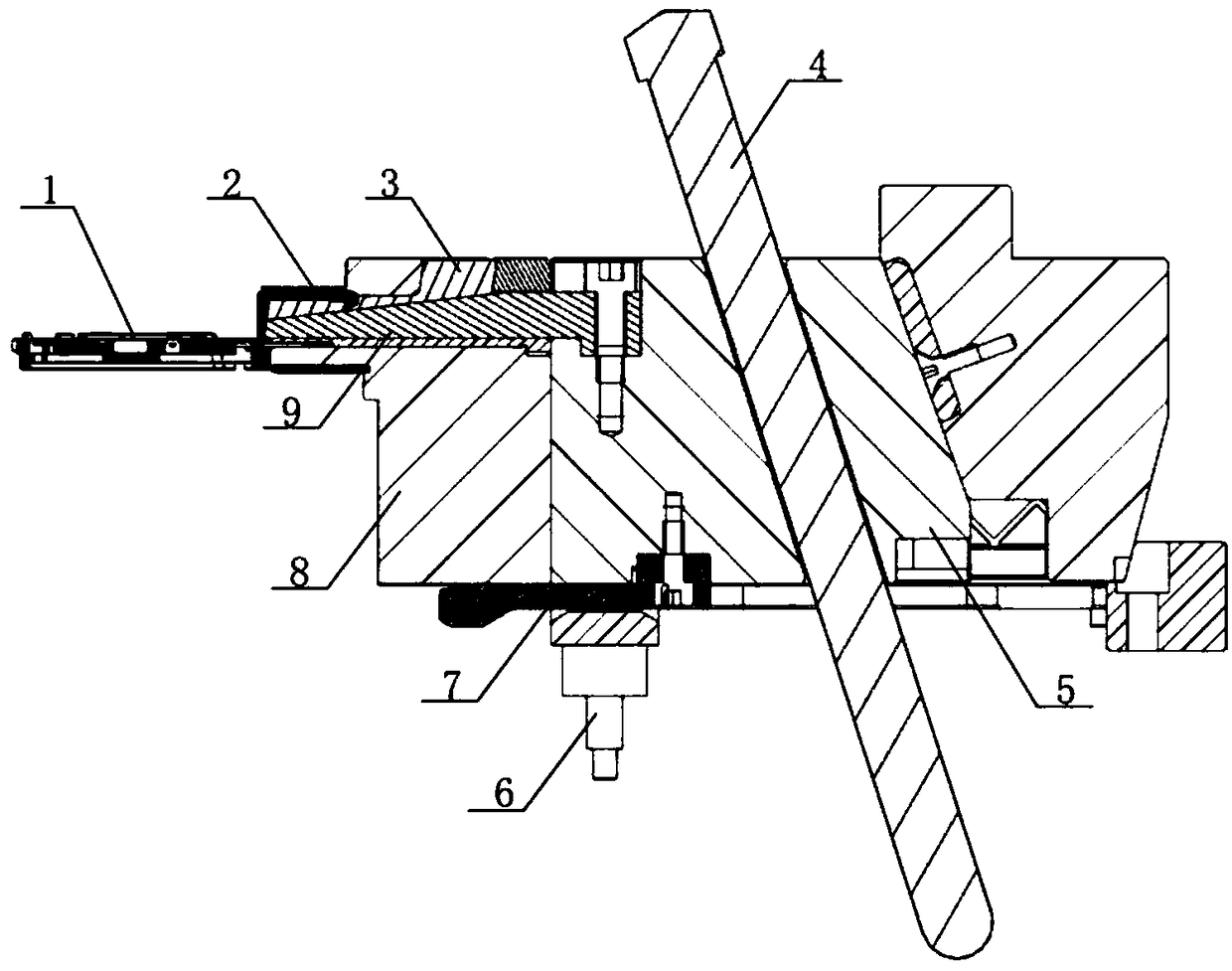
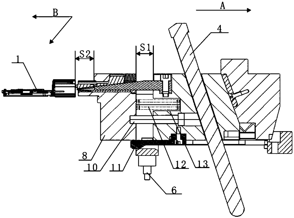
[0022] According to an embodiment of the present application, refer to figure 1 , the slider core-pulling two-way buckle-off core-pulling mechanism of this program includes an oblique guide post 4, a slider seat 5 and a front end slider 8, and the oblique guide post 4 is embedded in the slider seat 5, which is aligned with the vertical direction The slope is 18°-25°, preferably 20° in this embodiment. When opening the mold...


PUM


Abstract

The invention discloses a sliding block core pulling bidirectional inverted buckle removing core pulling mechanism and a control method thereof. The sliding block core pulling bidirectional inverted buckle removing core pulling mechanism comprises an inclined guide column, a sliding block seat and a front end sliding block, wherein the inclined guide column is embedded in the sliding block seat, the sliding block seat is connected to the front end sliding block by a shoulder screw, the threaded end of the shoulder screw is fixedly connected to the front end sliding block through threads, the other end of the shoulder screw is snapped and connected in the sliding block seat, a spring parallel to the shoulder screw is arranged in the sliding block seat, one end of the spring is welded in thesliding block seat, the other end of the spring is pressed against the front end sliding block, a delaying rod is embedded at the connecting position between the bottom portion of the sliding block seat and the bottom portion of the front end sliding block, and is provided with a snapping plate for restricting the movement of the front end sliding block, a pushing block is fixed on the bottom endof the sliding block seat, one end of the pushing block is snapped and connected on the bottom portion of the sliding block seat, the other end of the pushing block is a projecting block, the projecting block penetrates through the delaying rod, and is attached to the bottom portion of the front end sliding block, the top portion of the front end sliding block is provided with a sliding block inclination ejection guide seat, and the sliding block inclination ejection guide seat is snapped and connected in the sliding block seat, and is provided with a sliding block inclination ejection for the snapping connecting of an inverted buckle.

Description

technical field [0001] The invention belongs to the technical field of undercut core-pulling, and in particular relates to a slider core-pulling two-way undercut core-pulling mechanism and a control method thereof. Background technique [0002] There is an undercut in the direction of the slider in the core-pulling forming area of ​​the slider of the plastic product. The existence of the undercut makes the slider unable to separate from the product, especially when the plastic product is an automotive connector with a complex structure. The rationality and dimensional accuracy requirements are high. Therefore, it is not feasible to solve the demoulding problem by changing the structure of the plastic product. At the same time, because the area where the undercut is located is small, if the traditional sliding mechanism is used to solve the demoulding problem, not only the project development cost is high, but the mold workpiece processing The time is long, the risk of mold ...

Claims


Application Information

Patent Timeline
Patent Type & Authority Applications(China)
IPC IPC(8): B29C45/33
CPCB29C45/332
Inventor 杨盛林袁坤林
Owner 宝利根(成都)精密工业有限公司
Learn More