Supercharge Your Innovation With Domain-Expert AI Agents!

Turbine shaft

A technology of turbine shaft and cavity, which is applied to the supporting elements of blades, engine elements, machines/engines, etc., and can solve problems such as affecting efficiency and service life, and excessive heat generation.

Inactive Publication Date: 2019-01-25
沈丹萍
View PDF0 Cites 0 Cited by
  • Summary
  • Abstract
  • Description
  • Claims
  • Application Information

AI Technical Summary

Problems solved by technology

[0002] With the development of science and the progress of society, the country has been promoting the development of advanced technology. Among them, there has always been a relatively difficult technical problem in the field of turbine technology. The general turbine has the problem of cooling the turbine shaft, and the oil cooling method is often used. However, only relying on the limited cooling of the engine oil cannot completely cool the shaft, which will cause excessive heat generation and affect the efficiency and service life. The main purpose is lubrication. The device of the present invention solves this problem

Method used


Image

  • Turbine shaft
  • Turbine shaft

Examples


Embodiment Construction

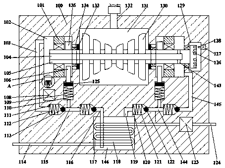
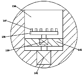
[0012] Such as figure 1 with figure 2 As shown, a turboshaft of the present invention includes a fuselage 100 and a first cavity 131 disposed in the fuselage 100, and a symmetrical second cavity 102 is provided at the left and right ends of the first cavity 131. , the right end of the second cavity 102 is provided with a third cavity 129, the first cavity 131 is rotated and connected with a turbine shaft 105 extending left and right, and the left and right ends of the turbine shaft 105 extend into the second cavity. In the cavity 102, the turbine shaft 105 is penetrated with a cooling oil flow hole 104 opening to the left, and the second cavity 102 is fixedly connected with a fixed block 101 that is rotatably connected with the turbine shaft 105, so The inner wall between the first cavity 131 and the second cavity 102 is provided with a bearing 134 rotatably connected with the turbine shaft 105, and the end of the bearing 134 close to the first cavity 131 is provided with an...


PUM


Abstract

The invention discloses a turbine shaft. The turbine shaft comprises a machine body and a first cavity formed in the machine body, symmetrical second cavities are formed in the left end and the rightend of the first cavity, a third cavity is formed in the right end of the right-end second cavity, the turbine shaft extending left and right is in rotational fit in the first cavity, the left end andthe right end of the turbine shaft extend into the second cavities, a cooling flow oil hole with an opening formed leftwards penetrates through the turbine shaft, fixed blocks which are in rotationalfit with the turbine shaft are fixedly connected in the second cavities, bearings which are in rotational fit with the turbine shaft are arranged in the inner walls between the first cavity and the second cavities, oil sealing rings are arranged at the portions, close to the first cavity ends, of the bearings, and protruding parts located on the fixed blocks and close to the first cavity end arearranged on the turbine shaft.

Description

technical field [0001] The invention relates to the technical field of turbines, in particular to a turbine shaft. Background technique [0002] With the development of science and the progress of society, the country has been promoting the development of advanced technology. Among them, there has always been a relatively difficult technical problem in the field of turbine technology. The general turbine has the problem of cooling the turbine shaft, and the oil cooling method is often used. However, only relying on the limited cooling of the engine oil cannot completely cool the shaft, which will cause excessive heat generation and affect the efficiency and service life. Its main purpose is still lubrication, and the device of the present invention solves this problem. Contents of the invention [0003] The technical problem to be solved by the present invention is to provide a turbine shaft, which can solve the above-mentioned problems in the prior art. [0004] The pres...

Claims


Application Information

Patent Timeline
IPC IPC(8): F01D25/12F01D5/06
CPCF01D25/12F01D5/06
Inventor 沈丹萍
Owner 沈丹萍
Features
  • R&D
  • Intellectual Property
  • Life Sciences
  • Materials
  • Tech Scout
  • Unparalleled Data Quality
  • Higher Quality Content
  • 60% Fewer Hallucinations
Learn More