

Method for generating a nozzle hole in a wall top-moving connection
A wall and root canal technology, applied in the direction of cable laying equipment, electrical components, etc., can solve the problems of cumbersome pipeline layout operations, time-consuming, unfavorable production operations, etc., and achieve the effect of improving work efficiency and accuracy
- Summary
- Abstract
- Description
- Claims
- Application Information
AI Technical Summary
Problems solved by technology
Method used
Image

Examples
Embodiment Construction
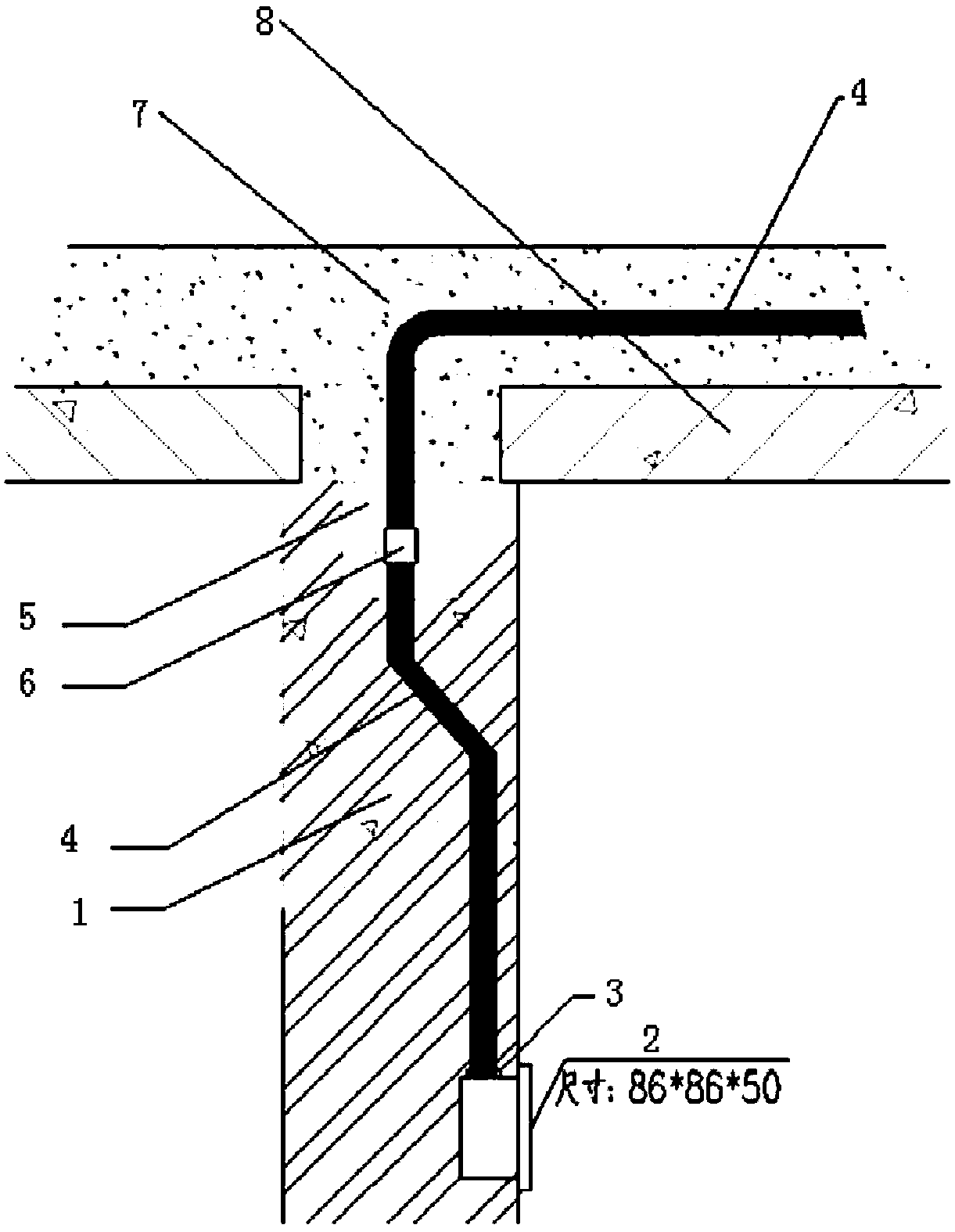
[0015] Such as figure 1 , the takeover hole is at the top of the wall, and the position is centered on one side.
[0016] The wall type is a partition wall or a beam-strip wall under a laminated floor.
[0017] The connection between equipment meets the principle of optimal path and horizontal and vertical layout of official roads. The optimal path at this time refers to the vertical pipes extending from the respective interfaces of the two equipments connected through the roof until the floor is cast-in-place. Layer part 7, two sections of pipes reaching the cast-in-place floor of the floor are automatically connected, and the pipes form elbows at the joints in the vertical and horizontal directions.
[0018] The installation depth of the pipe in the cast-in-place layer of the laminated floor and the distance between the pipe and the wall surface when the pipe is inside the wall shall not be less than 15mm.
[0019] The height of the wire box can be set to be 40mm higher th...
PUM
 Abstract
Description
Claims
Application Information