
Solenoid valve control method and device

A control method and solenoid valve technology, applied in transmission control, components with teeth, belts/chains/gears, etc., can solve problems such as the inability to fundamentally guarantee the driving safety of vehicles and the inability to guarantee the driving safety of automatic transmission vehicles

Active Publication Date: 2019-02-05
SHENGRUI TRANSMISSION
View PDF6 Cites 0 Cited by
  • Summary
  • Abstract
  • Description
  • Claims
  • Application Information

AI Technical Summary

Problems solved by technology

Although the automatic transmission vehicle has liberated manpower consumption to a certain extent, there are still many problems in the switching between gears during the driving process of the automatic transmission vehicle, which cannot fundamentally guarantee the driving safety of the vehicle.
[0004] To sum up, at present, there is no effective solution to the problem of not being able to guarantee the driving safety during the shifting period of automatic transmission vehicles.

Method used


Image

  • Solenoid valve control method and device
  • Solenoid valve control method and device
  • Solenoid valve control method and device

Examples


Embodiment 1

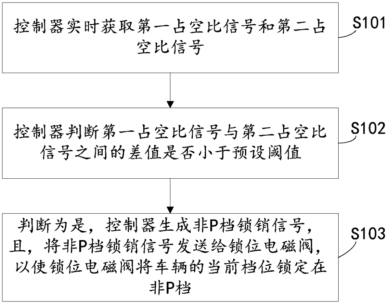
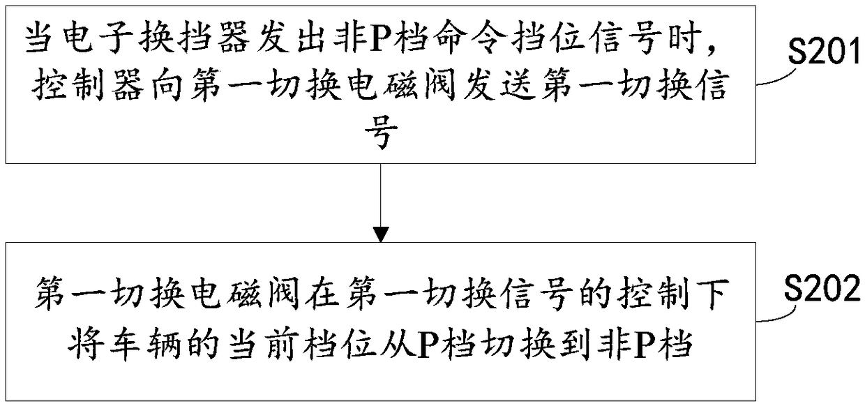
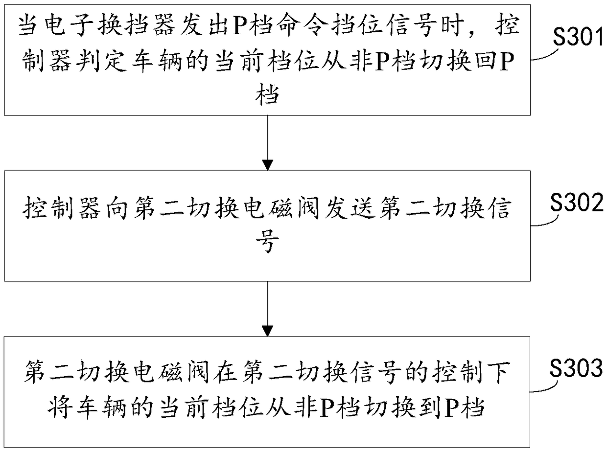
[0045] see figure 1 , figure 2 with image 3 , the solenoid valve control method proposed in this embodiment specifically includes the following steps:

[0046] Step S101: The controller obtains the first duty ratio signal and the second duty ratio signal in real time, wherein the first duty ratio signal is the duty ratio value corresponding to the non-P gear, and the controller obtains the real-time value from the P gear switch position sensor The duty ratio signal is a second duty ratio signal.

[0047]Usually, the default initial gear position of the vehicle is the P gear, that is, under normal circumstances, the duty cycle is equal to about 10% in the initial state. In the case of a fault, the duty cycle may be equal to any value between 0% and 100% in the initial state. After the vehicle is started, if the driver switches the shift lever to non-P, the transmission control unit will control the first switching solenoid valve, so that the relevant hydraulic oil circuit...

Embodiment 2

[0073] see Figure 4 , the present embodiment provides a solenoid valve control device comprising:

[0074] The duty ratio acquisition module 1 is used for the controller to obtain the first duty ratio signal and the second duty ratio signal in real time, wherein the first duty ratio signal is the duty ratio value corresponding to the non-P gear, and the controller starts from the P gear The duty ratio signal acquired by the switch position sensor in real time is the second duty ratio signal;

[0075] Judging module 2, used for the controller to judge whether the difference between the first duty ratio signal and the second duty ratio signal is greater than a preset threshold;

[0076] The locking module 3 is configured to determine yes, the controller generates a non-P gear lock pin signal, and sends the non-P gear lock pin signal to the lock position solenoid valve, so that the lock position solenoid valve locks the current gear position of the vehicle at Non-P file.


PUM


Abstract

The invention provides a solenoid valve control method and device, and relates to the technical field of automobile control. The solenoid valve control method comprises the steps that firstly, a controller acquires a first duty cycle signal and a second duty cycle signal in real time, what needs to be explained is that the first duty cycle signal is a duty cycle value corresponding to a non-P gear, and the duty cycle signal obtained by the controller from a P gear switch position sensor in real time is the second duty cycle signal; and secondly, the controller judges whether the difference between the first duty cycle signal and the second duty cycle signal is greater than a preset threshold or not, then, if it is judged that difference between the first duty cycle signal and the second duty cycle signal is greater than the preset threshold, in other words, the gear position is abnormally switched to a P gear, the controller generates a non-P gear lock pin signal, and the non-P gear lock pin signal is sent to a lock position solenoid valve so that the lock position solenoid valve can lock the current gear of a vehicle to the non-P gear; and by means of the above treatment, the condition that the vehicle is illegally switched to the P gear is effectively avoided, the vehicle dangerous parking condition is prevented, and the driving safety during the vehicle gear switching periodis guaranteed.

Description

technical field [0001] The invention relates to the technical field of automobile control, in particular to a solenoid valve control method and device. Background technique [0002] With the development of the economy and the improvement of people's living standards, the automobile industry is also booming, and more and more private cars appear in people's lives. The safe driving of vehicles has also become a hot spot of concern. [0003] In recent years, automatic transmission vehicles have become more and more popular. Compared with vehicles with manual transmission, vehicles with automatic transmission generally use automatic transmission to adjust the vehicle speed. When driving, the control system of automatic transmission automatically selects the appropriate gear according to the engine speed and load, thus replacing the subjective judgment of human beings. Shift operation. Although the automatic transmission vehicle has liberated manpower consumption to a certain ...

Claims


Application Information

Patent Timeline
Patent Type & Authority Applications(China)
IPC IPC(8): F16H61/02F16H61/16
CPCF16H61/0213F16H61/16
Inventor 杜滕州杨治学邱兵郭伟
Owner SHENGRUI TRANSMISSION
Learn More