Clamping mechanism with locking function and water cup with clamping mechanism
The technology of a clamping mechanism and a locking mechanism is applied in the field of the clamping mechanism and the water cup provided with the clamping mechanism, which can solve the problems such as the bulky cover of the water cup, the damage of the clamping device, and the easy occurrence of bumps, etc., and achieves simple structure, Easy-to-use, non-scratch effect
- Summary
- Abstract
- Description
- Claims
- Application Information
AI Technical Summary
Problems solved by technology
Method used
Image

Examples
Embodiment 1
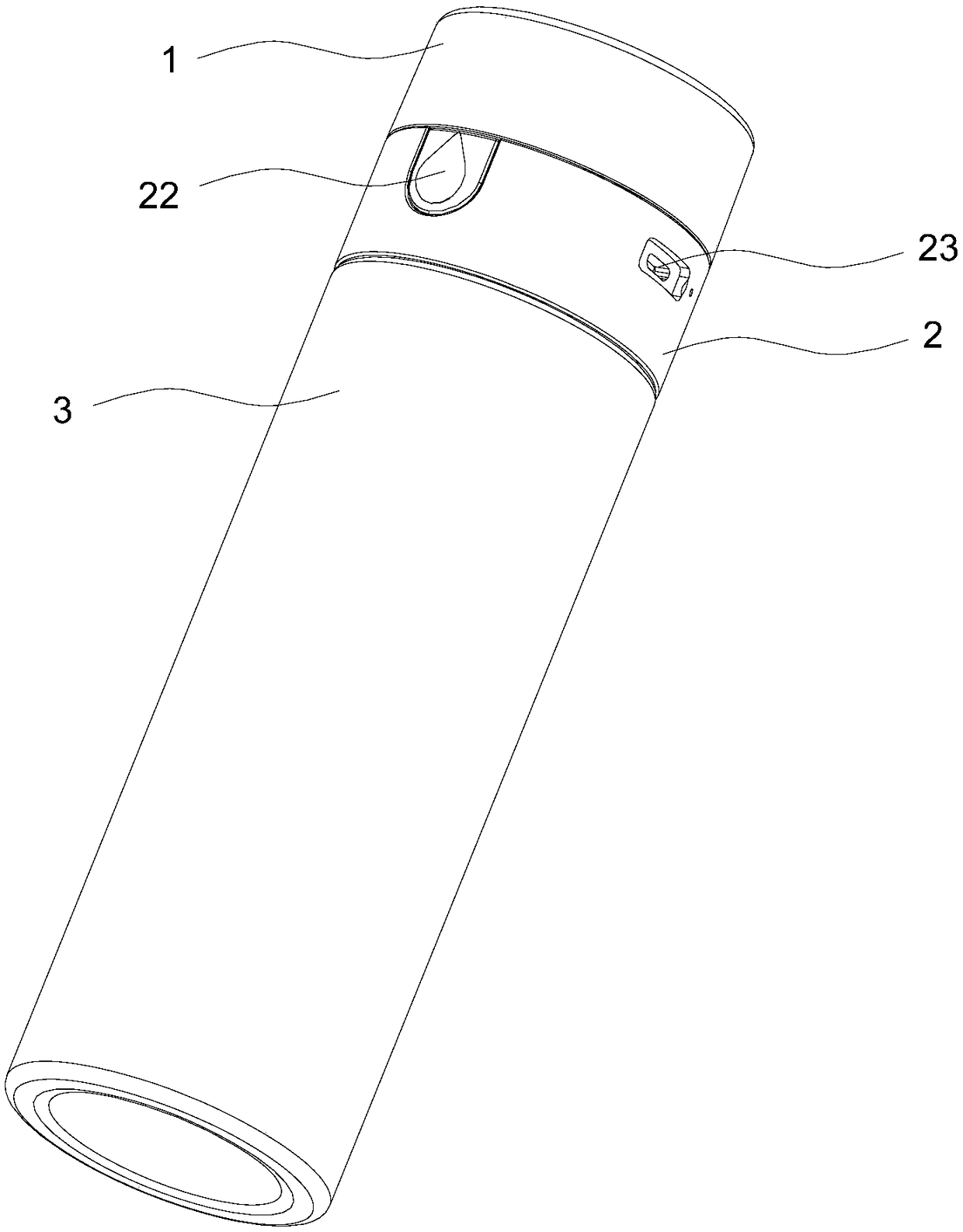
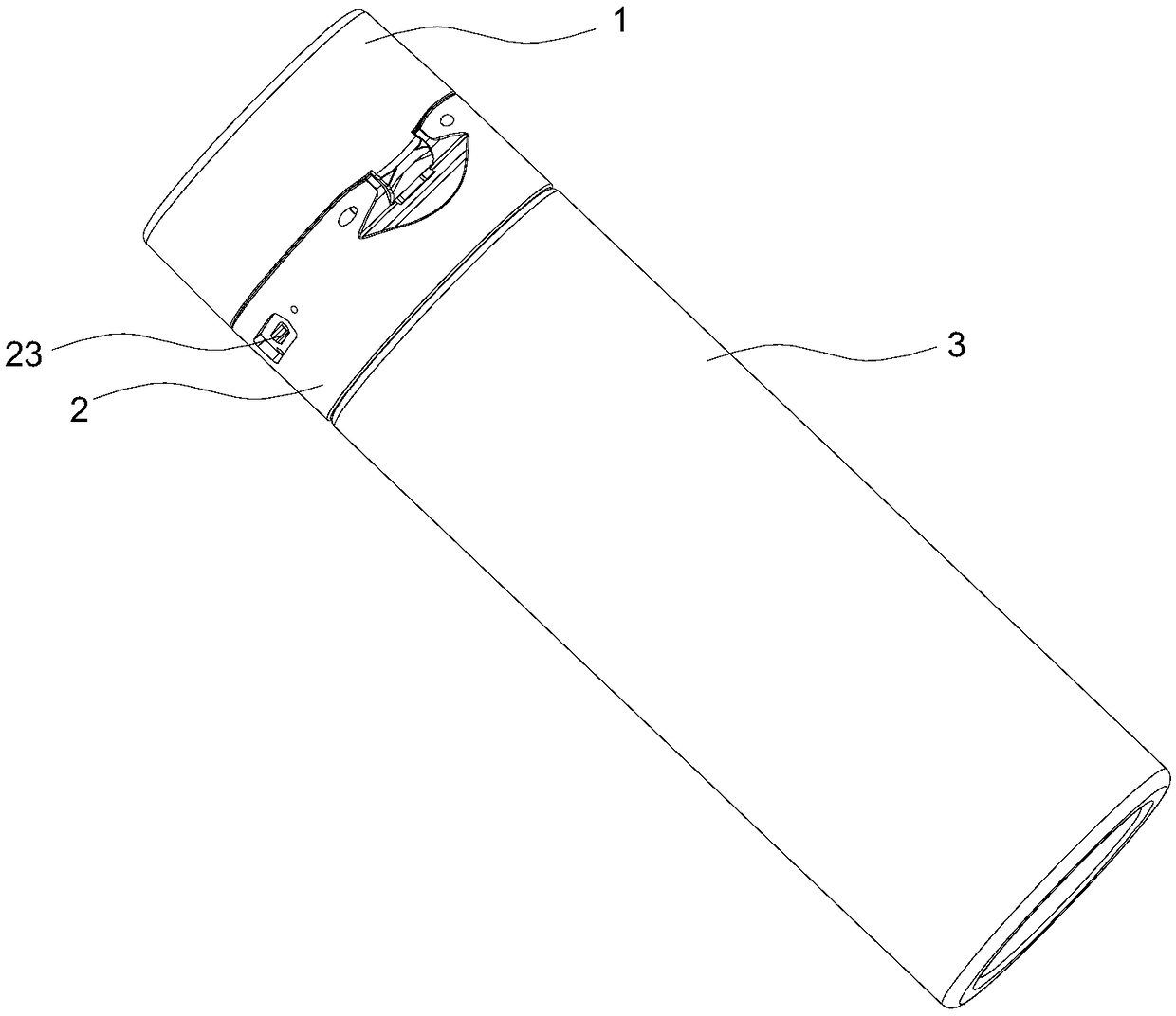
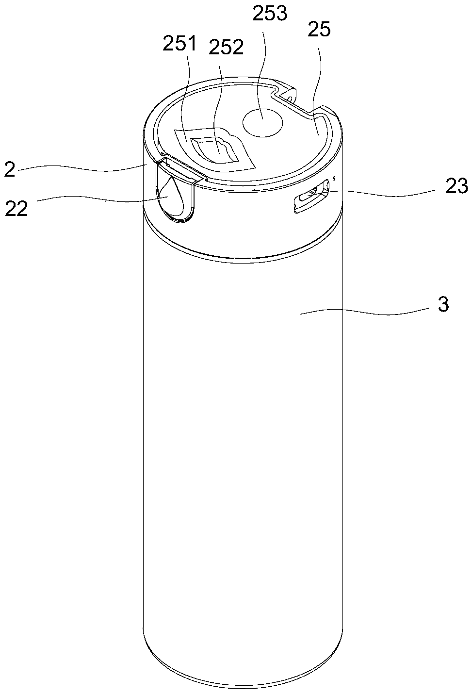
[0039] Such as Figure 5 , Figure 6 , Figure 7 , Figure 10 , Figure 11 As shown, this embodiment discloses a clamping mechanism with a locking function, which includes a main body A1 and a main body B2 that are hinged and fastened to each other. The main body B2 is provided with a groove A26, and the groove A26 is provided with a There is a pressing block 22 that controls the opening and closing of the main body A1 and the main body B2. The pressing block 22 is hinged to the groove A26 through the connecting column C261. A locking mechanism for locking the pressing block 22 .
[0040]The pressing block 22 is sheathed on the connecting column C261, and is rotatably connected with the connecting column C261. Pressing the pressing block 22 can make the main body A1 open. Press the main body A1 to the main body B2, the main body B2 is fastened with the main body A1 through the pressing block 22, and the pressing block 22 is locked by the locking mechanism, and the pressin...
Embodiment 2
[0042] This embodiment is a definition optimized on the basis of the above-mentioned embodiment 1, such as Figure 3 to Figure 11 As shown, a locking mechanism with a locking function in this embodiment, the pressing block 22 includes a pressing block main body 229 and a slider 221 slidingly connected with the pressing block main body 229; the locking mechanism includes a set The hook C262 in the groove A26 and the hook D2211 provided on the slider 221; the hook D2211 is an inverted L-shaped structure; Block 22 pushes the bump D263.
[0043] The hook D2211 is disposed on the side of the slider 221 close to the groove A26, and the hook C262 cooperates with the hook D2211. The hook D2211 is disposed on the slider 221 , and when the slider 221 is slid, the hook D2211 moves under the drive of the slider 221 . Slide the slider 221 in the direction where the hook C262 is located, so that the hook D2211 is engaged with the hook C262. At this time, the hook D2211 is located in the g...
Embodiment 3
[0045] This embodiment is a definition optimized on the basis of the above-mentioned embodiment 2, such as Figure 3 to Figure 11 As shown, in the locking mechanism of this embodiment, the main body 229 of the pressing block is provided with a through hole C227, the hook D2211 passes through the through hole C227 and Sliding inside; the side of the pressing block body 229 close to the groove A26 is provided with a limiting block 228 for limiting the moving direction of the hook D2211; the sliding block 221 is in the shape of a drop. The slider 221 is drop-shaped. The side of the slider 221 close to the main body 229 of the pressing block is a plane, and the side away from the main body 229 of the pressing block is a protruding three-dimensional structure, which is convenient for sliding the slider 221 during use. The limiting block 228 is arranged on the side of the pressing block main body 229 close to the groove A26, and is located in the gap between the hook D2211 cross bar...
PUM
 Abstract
Description
Claims
Application Information
 - R&D Engineer
- R&D Manager
- IP Professional
- Industry Leading Data Capabilities
- Powerful AI technology
- Patent DNA Extraction
Browse by: Latest US Patents, China's latest patents, Technical Efficacy Thesaurus, Application Domain, Technology Topic.
© 2024 PatSnap. All rights reserved.Legal|Privacy policy|Modern Slavery Act Transparency Statement|Sitemap