An automatic punching device for sol forming

An automatic punching and sol technology, which is applied in metal processing and other fields, can solve the problems of increasing production costs and low quality

Active Publication Date: 2021-03-23
深圳金皇尚热熔胶喷涂设备有限公司
View PDF6 Cites 0 Cited by
  • Summary
  • Abstract
  • Description
  • Claims
  • Application Information

AI Technical Summary

Problems solved by technology

[0002] Plastisol is a dispersion of polyvinyl chloride resin, the liquid phase of which is completely plasticizer, also known as plastisol, in order to make the viscosity of plastisol meet the requirements of molding flow, the content of plasticizer in plastisol is generally quite a lot 40% of the resin, so the molded products are generally soft. With the help of mechanical force and solvation, the polyvinyl chloride resin particles can be uniformly dispersed and suspended in the dispersant. Properly controlling the degree of granulation of the resin can Polyvinyl chloride plastisol with a viscosity suitable for molding is obtained. Injection molding is a method of injecting thermoplastic melt into a mold under high pressure with an injection molding machine, cooling and solidifying to obtain a product. Injection molding can also be used for molding thermosetting plastics and foam plastics. The advantages of injection molding are fast production speed, high efficiency, automatic operation, and the ability to form parts with complex shapes. It is especially suitable for mass production. At present, in the actual production process of many sol injection molding, there are often a large number of air bubbles in the formed products, and the quality is low. , and the nozzle on the edge of the product needs to be removed through subsequent processing, which will increase the production cost virtually. Therefore, it is necessary to design an integrated equipment with nozzle cutting function

Method used


Image

  • An automatic punching device for sol forming
  • An automatic punching device for sol forming
  • An automatic punching device for sol forming

Examples


Embodiment Construction

[0024] Below in conjunction with accompanying drawing and embodiment of description, specific embodiment of the present invention is described in further detail:

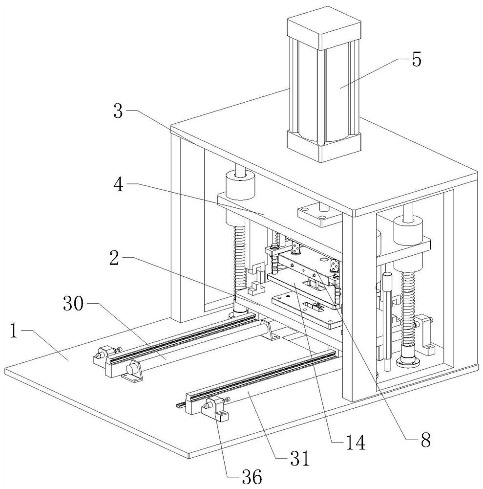
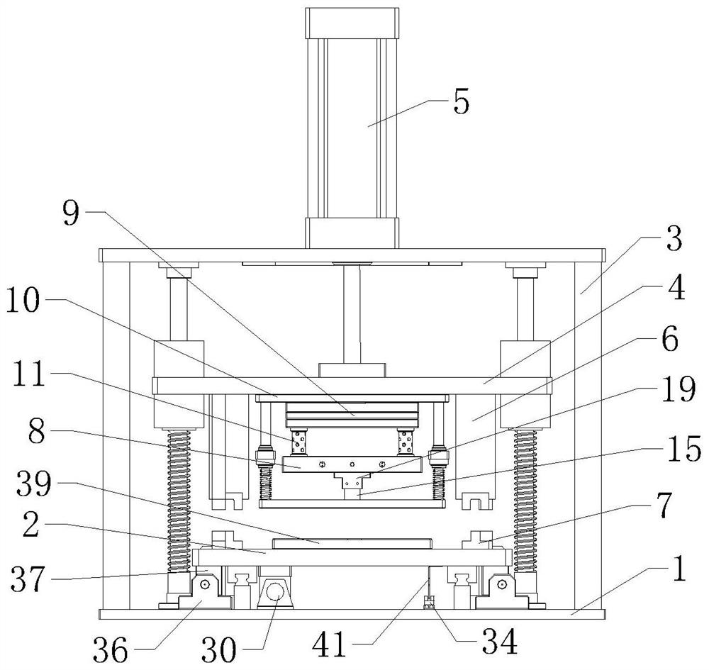
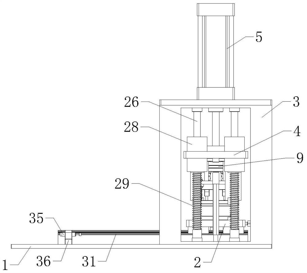
[0025] refer to Figure 1 to Figure 8 The shown automatic punching device for sol molding includes a stamping assembly, a hot-melt assembly and a cutting assembly. The stamping assembly includes a bottom plate 1, a supporting platform 2, a support frame 3, a stamping plate 4, a stamping cylinder 5, and a positioning mechanism. The frame 3 is vertically arranged on the top of the base plate 1, the stamping cylinder 5 is vertically arranged on the top of the support frame 3 and its output end passes through the support frame 3 vertically downwards and is fixedly connected with the punching plate 4 below, and the supporting platform 2 is located on Right below the stamping plate 4 and the bottom of the support platform 2 is slidingly connected to the top of the base plate 1. The positioning mechanism includes four posi...


PUM


Abstract

The invention relates to the field of gluing equipment, in particular to an automatic punching device for sol forming. The automatic punching device comprises a punching assembly, a hot melting assembly and a cutting assembly; the punching assembly comprises a bottom plate, a support platform, a support frame, a punching plate, a punching air cylinder and a positioning mechanism, and the positioning mechanism comprises four positioning columns and four positioning blocks; the hot melting assembly comprises a heating plate, a heat insulation plate, a connecting plate and four heat dissipating columns, a discharging hole which is through up and down is formed in the middle of the heating plate, and a feeding hole communicating with the discharging hole is formed in the side surface of the heating plate; the cutting assembly comprises a buffer plate and two cutting blades, the buffer plate and the connecting plate are elastically connected through a buffer mechanism, and the buffer plateand the support platform are provided with avoiding holes used for avoiding the cutting blades. By means of the automatic punching device for sol forming, sol is pressed into a mold cavity to be formed, water nozzle cutting can be carried out on the two ends of the formed sol, and the automatic punching device is simple structure and convenient to use.

Description

technical field [0001] The invention relates to the field of gluing equipment, in particular to an automatic punching device for sol forming. Background technique [0002] Plastisol is a dispersion of polyvinyl chloride resin, the liquid phase of which is completely plasticizer, also known as plastisol, in order to make the viscosity of plastisol meet the requirements of molding flow, the content of plasticizer in plastisol is generally quite a lot 40% of the resin, so the molded products are generally soft. With the help of mechanical force and solvation, the polyvinyl chloride resin particles can be uniformly dispersed and suspended in the dispersant. Properly controlling the degree of granulation of the resin can Polyvinyl chloride plastisol with a viscosity suitable for molding is obtained. Injection molding is a method of injecting thermoplastic melt into a mold under high pressure with an injection molding machine, cooling and solidifying to obtain a product. Injection...

Claims


Application Information

Patent Timeline
Patent Type & Authority Patents(China)
IPC IPC(8): B26F1/40B26F1/44B26D7/10B29C45/38
CPCB26D7/10B26F1/40B26F1/44B29C45/382
Inventor 王荣铭
Owner 深圳金皇尚热熔胶喷涂设备有限公司
Why Eureka
Try Eureka