

Furniture hinge
A hinge and furniture technology, applied in door/window fittings, folding panels, construction, etc., can solve the problems of small expandability of the gripper, small lifting movement of the extension parts, high cost, etc., and achieve uniform adjustment and firm hold. , the effect of reducing the contact pressure
- Summary
- Abstract
- Description
- Claims
- Application Information
AI Technical Summary
Problems solved by technology
Method used
Image

Examples
Embodiment Construction
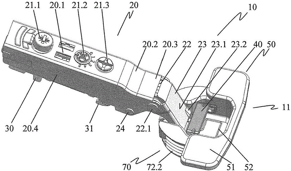
[0033] figure 1 The front perspective view shows the furniture hinge 10 in the first position of the raised arrangement.
[0034] A hinge arm 20 and a stop 11 are associated with the furniture hinge 10 . The hinge arm 20 is articulated to the stop 11 . Along the rear span 20.1 of the hinged arm 20, a depth adjustment screw 21.1, a positioner 21.2 and a support adjustment screw 21.3 are arranged. The side legs 20.4 are connected to the rear span 20.1 on both sides. The hinge arm 20 is engaged in a connecting piece 30 comprising a connecting hook 31 . Towards the joint, the rear span 20.1 transitions via a transition section 20.2 into a section 20.3 that is recessed relative to the rear span 20.1. The recessed section 20.3 is connected via the external articulation 22 to the external hinge lever 23, which comprises an actuation surface 23.1 with a protrusion 23.2, which is oriented towards the hinge cup 52 with the actuation piece 40. The outer articulation part 22 is forme...
PUM
 Abstract
Description
Claims
Application Information