Vehicle seat and slide rail locking and stopping and unlocking mechanism thereof

A technology of unlocking mechanism and vehicle seat, which is applied to vehicle seats, movable seats, vehicle parts, etc., can solve the problem of low operation flexibility, and achieve a simple movement mode, ensure dexterity, and high locking reliability. Effect

Pending Publication Date: 2019-02-12
GAC COMPONENT CO LTD
View PDF0 Cites 1 Cited by
  • Summary
  • Abstract
  • Description
  • Claims
  • Application Information

AI Technical Summary

Problems solved by technology

[0006] The technical problem to be solved by the present invention is to provide a vehicle seat and its sliding rail locking and unlocking mechanism to solve the problem of low operational flexibility of the existing sliding rail locking and unlocking mechanism

Method used


Image

  • Vehicle seat and slide rail locking and stopping and unlocking mechanism thereof
  • Vehicle seat and slide rail locking and stopping and unlocking mechanism thereof
  • Vehicle seat and slide rail locking and stopping and unlocking mechanism thereof

Examples


Embodiment 1

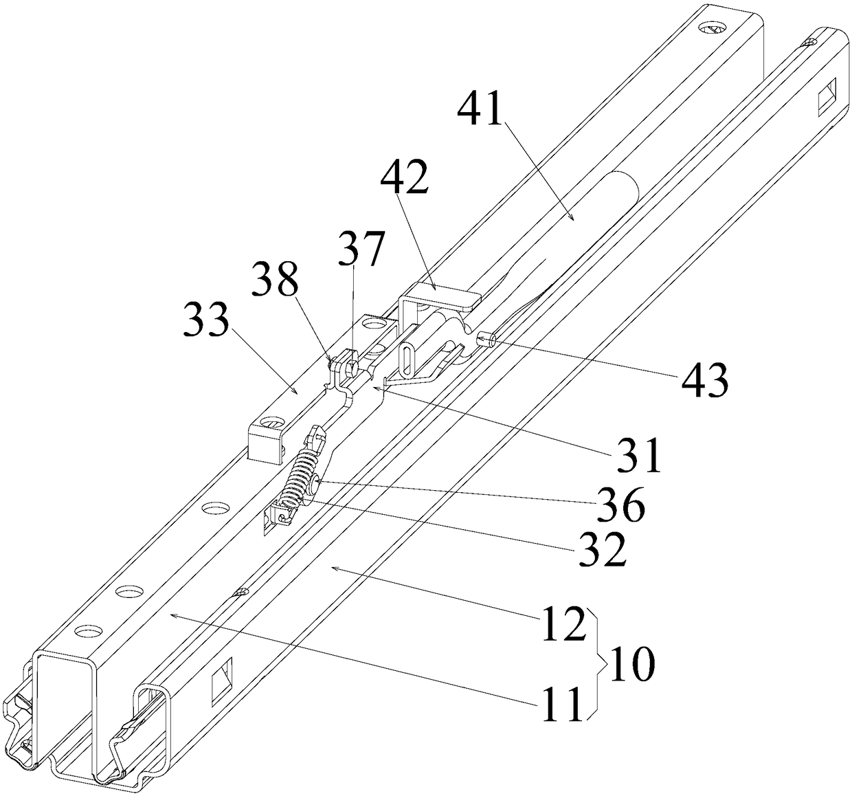
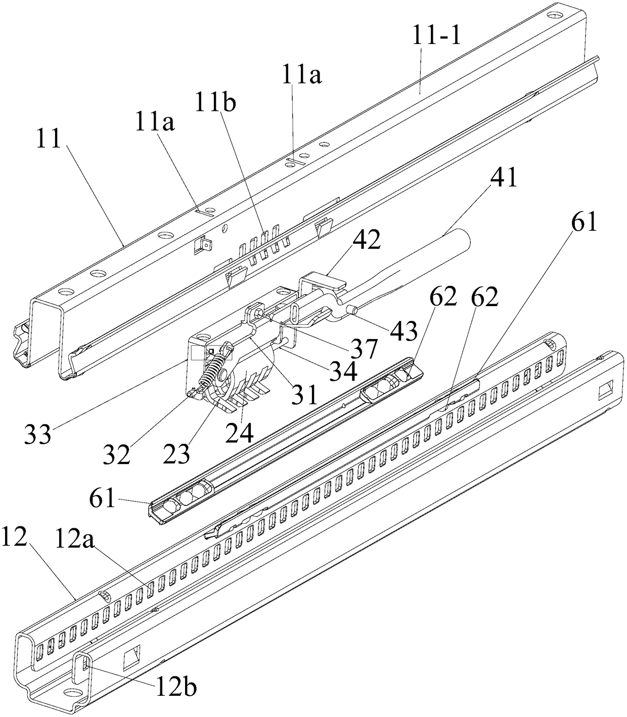
[0037] like Figure 1 to Figure 6 As shown, the present invention discloses a sliding rail locking and unlocking mechanism for a vehicle seat, including a sliding rail assembly 10, a locking assembly 20, an unlocking assembly 30, and a manipulation assembly 40. The upper slide rail 11 and the lower slide rail 12 are provided, and the upper slide rail 11 can move forward and backward along the extending direction of the lower slide rail 12 .

[0038] The left parts of the upper slide rail 11 and the lower slide rail 12 are provided with a plurality of left card slots arranged at intervals along the extending direction, which are respectively denoted as the left card slot holes of the upper slide rail 11 and the slide down slots. The left card slot hole 12a of the rail 12; the right side parts of the upper slide rail 11 and the lower slide rail 12 are provided with a plurality of right card slot holes arranged at intervals along the extending direction, respectively denoted as t...

Embodiment 2

[0043] On the basis of the first embodiment above, the second embodiment also adopts the following preferred structure:

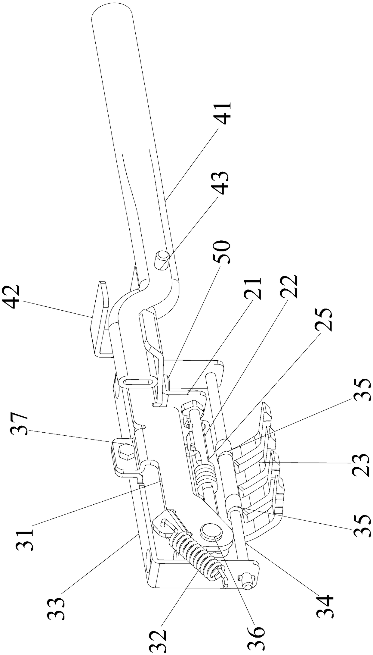
[0044] The unlocking assembly 30 is provided with a swing arm 31, a return spring 32, a movable frame 33 and a latch 34; the swing arm 31 is located outside the upper slide rail 11, and the rear end 31-1 of the swing arm 31 is rotatable is connected on the upper slide rail 11; the movable frame 33 is composed of a first insert part 33-1, a connecting part 33-2 and a second insert part 33-3, and the connecting part 33-2 is connected Between the upper end of the first insertion part 33-1 and the upper end of the second insertion part 33-3, the top surface 11-1 of the upper slide rail 11 is provided with two through holes 11a. The connecting part 33-2 is located above the upper slide rail 11, and the connecting part 33-2 is fixedly connected to the middle part 31-2 of the swing arm 31, and the lower end of the first insert part 33-1 and The lower end of the s...

Embodiment 3

[0048] On the basis of the above-mentioned embodiment two, the present embodiment three also adopts the following preferred structure:

[0049] At least one cam 35 is mounted on the pin 34 , and the cam 35 can rotate around the axis of the pin 34 . Thus, when the latch 34 moves downward or upward to expand or restore the left claw 23 and the right claw 24, the latch 34 contacts the left claw 23 and the right claw 24 through the cam 35, and the cam 35 Rotation occurs during this process, which can reduce the wear of the bolt 34, the left claw 23 and the right claw 24, and improve the smoothness of the left claw 23 and the right claw 24 being stretched or restored.


PUM


Abstract

The invention discloses a vehicle seat and a sliding rail locking and stopping and unlocking mechanism thereof. The sliding rail and locking and stopping unlocking mechanism of the vehicle seat comprises a sliding rail assembly, a locking and stopping assembly, an unlocking assembly and a steering assembly. An upper sliding rail and a lower sliding rail are arranged on the sliding rail assembly, alocking and stopping assembly bracket, a core shaft, a left clamping claw, a right clamping claw and a torsion spring are arranged on the locking and stopping assembly, and a swing arm, a reset spring, a movable frame and a plug are arranged on the unlocking assembly. According to the vehicle seat and the sliding rail and unlocking mechanism thereof, the locking and stopping assembly is used forrealizing the front and back movement locking and stopping between the upper and lower sliding rails, and the locking and stopping reliability is high; occupants exert a downward force to the front end of the swing arm through the steering assembly, that is, the unlocking assembly can be controlled to unlock locking and stopping of the locking and stopping assembly to the upper and lower sliding rails, the unlocking of the sliding rail of the vehicle seat is realized, while the occupants can release the steering assembly, the downward force can be removed, so that the unlocking assembly can bereset under the action of the reset spring, and the sliding rail locking and stopping of the vehicle seat is reset; and the unlocking operation is simple and convenient, and the dexterity, smoothnessand good operation hand sense of the occupants operating the steering assembly for unlocking the vehicle seat sliding rail.

Description

technical field [0001] The invention relates to a sliding rail locking and unlocking mechanism of a vehicle seat, and a car seat using the sliding rail locking and unlocking mechanism. Background technique [0002] With the continuous development of vehicle technology and the continuous improvement of user requirements, higher requirements are put forward for the safety and comfort of vehicles, and vehicle seats are an indispensable part of vehicles. The safety and comfort of vehicle seats Comfort is especially important. [0003] The vehicle seat slide rail is an integral part of the vehicle seat. The slide rail lock is an important guarantee to prevent the driver and passengers from being injured when the vehicle is impacted. If the seat slide rail lock fails when the vehicle is impacted, it may easily cause a safety accident. . [0004] The front and rear adjustment of the vehicle seat is a basic function of most vehicle seats. This basic function is realized by the veh...

Claims


Application Information

Patent Timeline
Patent Type & Authority Applications(China)
IPC IPC(8): B60N2/08
CPCB60N2/08B60N2/0812B60N2/0881
Inventor 郭文庚赵培杰钟志清王长慧邱杰唐尧
Owner GAC COMPONENT CO LTD
Why Eureka
Try Eureka