Discharge diversion device for transformer rubber coating machine automatic feeding and discharging

A technology of a diversion device and a rubber encapsulation machine, which is used in the manufacture of inductors/transformers/magnets, packaging/impregnation, electrical components, etc. Effect

Active Publication Date: 2019-02-12
全椒县丰顺和电子有限公司
View PDF7 Cites 2 Cited by
  • Summary
  • Abstract
  • Description
  • Claims
  • Application Information

AI Technical Summary

Problems solved by technology

[0005] However, when the device is in use, since the material is discharged directly, the transformers after the encapsulation are easy to accumulate and cannot be collected effectively

Method used


Image

  • Discharge diversion device for transformer rubber coating machine automatic feeding and discharging
  • Discharge diversion device for transformer rubber coating machine automatic feeding and discharging
  • Discharge diversion device for transformer rubber coating machine automatic feeding and discharging

Examples


Embodiment 1

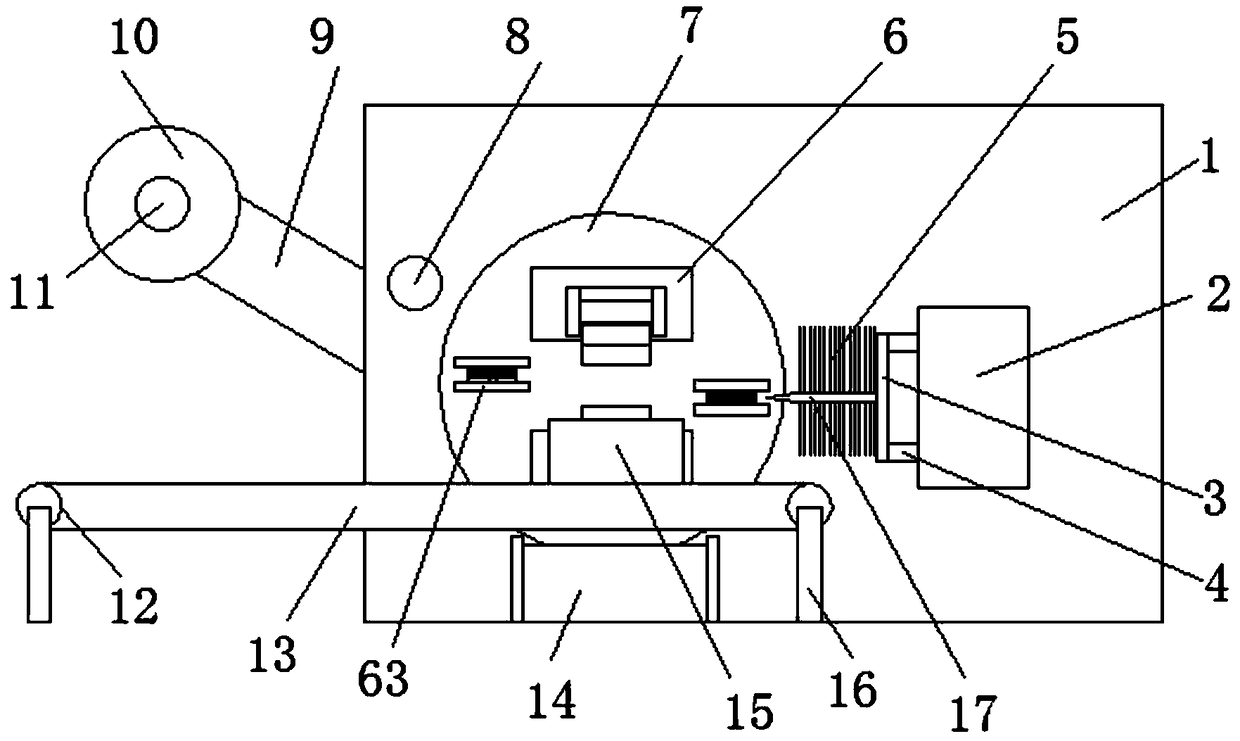
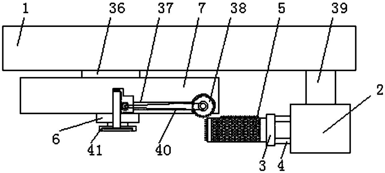
[0041] Embodiment 1, a discharge guide device for automatic feeding and discharging of a transformer encapsulation machine, comprising a encapsulation machine main body 1, a turntable 7, a transformer 23, an encapsulation fixing base 41 and a material belt support 9, the encapsulation machine main body 1 is provided with a turntable drive device 35, the turntable drive device 35 drives the turntable 7 to rotate through the main shaft 36, the main body 1 of the rubber encapsulation machine is fixedly installed with a material belt bracket 9 for installing the material belt, between the material belts There is a movable fixed roller 11 on the top, and an evenly wound material belt is arranged on the fixed roller 11. A feeding material fixed on the main body 1 of the rubber encapsulation machine is arranged between the material belt support 9 and the rubberized fixed base 41. Roller 8, described turntable 7 side is provided with knife rest 3, and described knife rest 3 side is pro...

Embodiment 2

[0045] The same as embodiment 1 is no longer repeated, and the difference with embodiment 1 is:

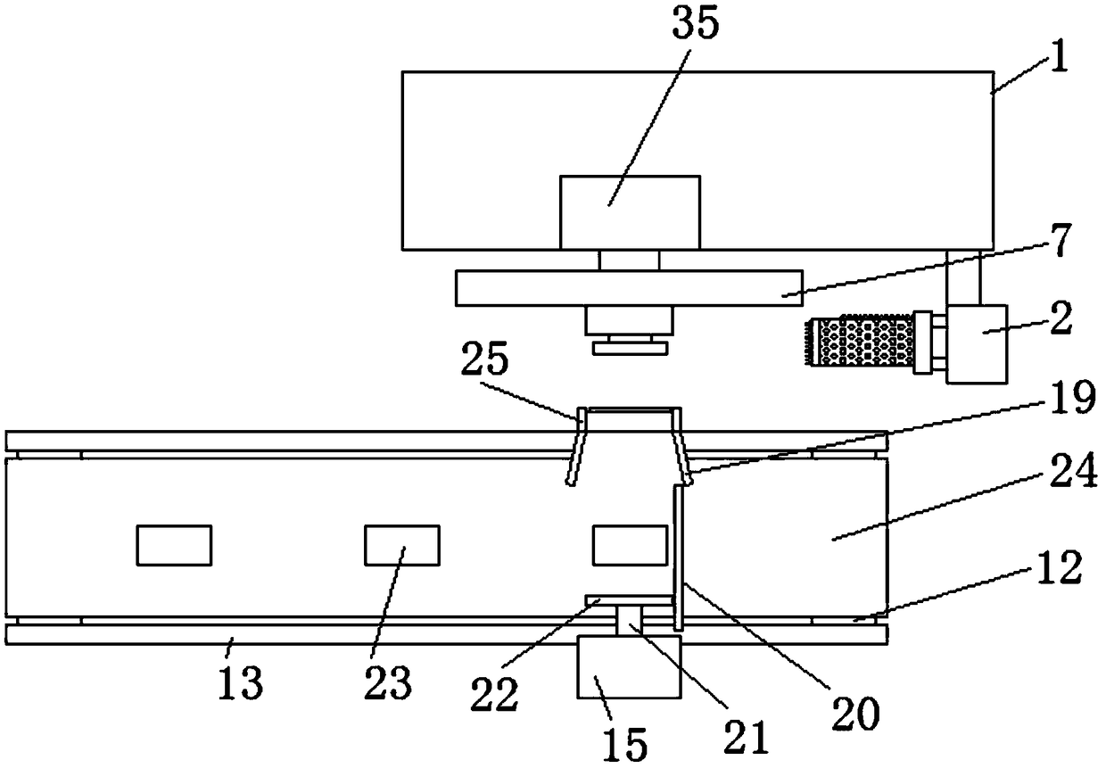
[0046] Preferably, the bottom of the rubberized fixed base 41 is provided with a discharge chute 14 that is inclined downward, and the two sides of the upper end of the discharge chute 14 are provided with a first fixed rod 56 that is vertically downward and fixedly connected. One side of the middle part of the first fixed rod 56 is provided with a vertical and fixedly connected second fixed rod 55, the front end of the second fixed rod 55 is connected to the bottom of the discharge chute 14, and the other side of the first fixed rod 56 Several vertical and fixedly connected third fixed rods 57 are provided, and the front ends of the third fixed rods 57 are fixedly connected with the main body 1 of the rubber encapsulation machine. The design of the discharge chute 14 can effectively guide the transformer 23 after encapsulation to the set position accurately, making the discharge ...

Embodiment 3

[0048] The same as embodiment 1 is no longer repeated, and the difference with embodiment 1 is:

[0049] Preferably, the deflector 19 is shaped like a "eight", and the cross section at the outlet of the deflector 19 is the same size as the transformer 23 .

[0050] Preferably, the cross-section of the push plate 22 is the same as the cross-section of the feeding trough 25 and the cross-section of the transformer 23 .

[0051] Preferably, the outer side of the conveyor belt 24 is provided with symmetrically distributed fixed frames 13, and the two ends of the conveyor belt 24 are provided with symmetrically distributed conveyor wheels 12, and the conveyor belt 24 is connected with the fixed frame 13 through the conveyor wheels 12, and the fixed frame The bottom of 13 is provided with several uniform and symmetrically distributed fixing frames 16.


PUM


Abstract

The invention discloses a discharge diversion device for transformer rubber coating machine automatic feeding and discharging. The device comprises a rubber coating machine main body, a rotary table,transformers, a rubber coating fixing base and a material strap support; the rubber coating machine main body is internally provided with a rotary table driving device, the rotary table driving devicedrives the rotary table to rotate through a driving shaft, the rubber coating fixing base is provided with a discharge sliding chute inclining downwards, vertically downwards arranged first fixed rods are fixedly connected to the two sides of the upper end of the discharge sliding chute, second fixed rods are vertically and fixedly connected to one sides of the middles of the first fixed rods, the front ends of the second fixed rods are connected with the bottom of the discharge sliding chute, multiple vertically and fixedly connected third fixed rods are arranged on the other sides of the first fixed rods, and the front ends of the third fixed rods are fixedly connected with the rubber coating machine main body. By means of design of the discharge sliding chute, the transformers obtainedafter rubber coating are completed can be effectively and accurately guided to the set positions, and discharge is more convenient, rapid and orderly.

Description

Technical field: [0001] The invention relates to the technical field of transformer encapsulation, in particular to a discharge guide device for automatic material in and out of a transformer encapsulation machine. Background technique: [0002] During the production and processing of transformers, it is necessary to wrap the transformer with glue. There are generally two forms of wrapping, manual wrapping and manual wrapping. Not only is the work efficiency low, but the length and effect of the wrapping depend entirely on the operator, quality Difficult to be guaranteed. [0003] There is also a mechanical automatic encapsulation. Chinese patent CN102137585B discloses an automatic encapsulation machine for wrapping insulating tape on the outer layer of the heat sink. The encapsulation machine includes a frame, a main shaft, a heat sink frame, a material belt support, a slide rail, The slider, the knife holder and the cutter, the main shaft is installed on the frame, the ma...

Claims


Application Information

Patent Timeline
Patent Type & Authority Applications(China)
IPC IPC(8): H01F41/00
CPCH01F41/005
Inventor 张磊
Owner 全椒县丰顺和电子有限公司
Why Eureka
Try Eureka