
Surveillance camera with patrol function

A surveillance camera and camera technology, applied in the field of surveillance cameras, can solve the problems of low reliability, high limitations, and high limitations in use, and achieve the effects of improving reliability, improving stability, and being easy to adjust.

Active Publication Date: 2019-02-12
ZHUCHENG HONGYUAN SECURITY TECH CO LTD
View PDF7 Cites 10 Cited by
  • Summary
  • Abstract
  • Description
  • Claims
  • Application Information

AI Technical Summary

Problems solved by technology

[0002] As everyone knows, a monitoring camera is a device for video recording, broadcasting and static image capture, which has been widely used in the field of cameras; the existing monitoring camera with patrol function includes a camera body, a support ring and a support rod , the camera body is installed inside the support ring, and the top of the support rod is connected to the bottom of the support ring; when the existing monitoring camera with patrol function is used, the bottom of the support rod is fixed at a certain position, and the support rod and the support ring support the camera body Generally speaking, users often install multiple groups of camera bodies in multiple locations. This installation method is costly and has high limitations; in the use of existing surveillance cameras with patrol functions, it is found that the camera lens needs to be wiped frequently, and the reliability of use is relatively high. Low; the camera is inconvenient to adjust the angle, and the convenience of use is poor; the camera is difficult to move, and often requires multiple sets of cameras to complete the monitoring of a large area, and the use limitations are high;

Method used


Image

  • Surveillance camera with patrol function
  • Surveillance camera with patrol function
  • Surveillance camera with patrol function

Examples


Embodiment Construction

[0022] The specific implementation manners of the present invention will be further described in detail below in conjunction with the accompanying drawings and embodiments. The following examples are used to illustrate the present invention, but are not intended to limit the scope of the present invention.

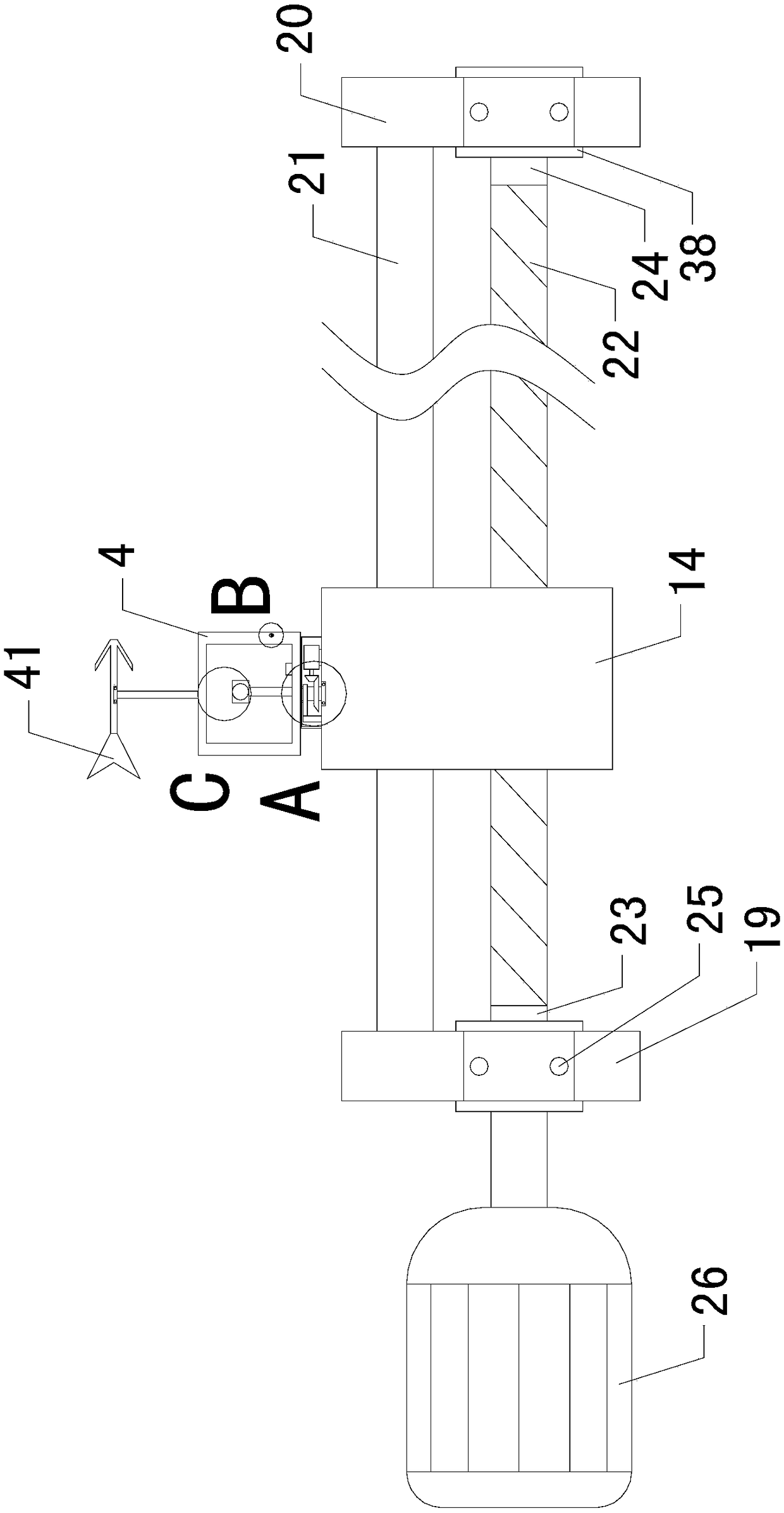
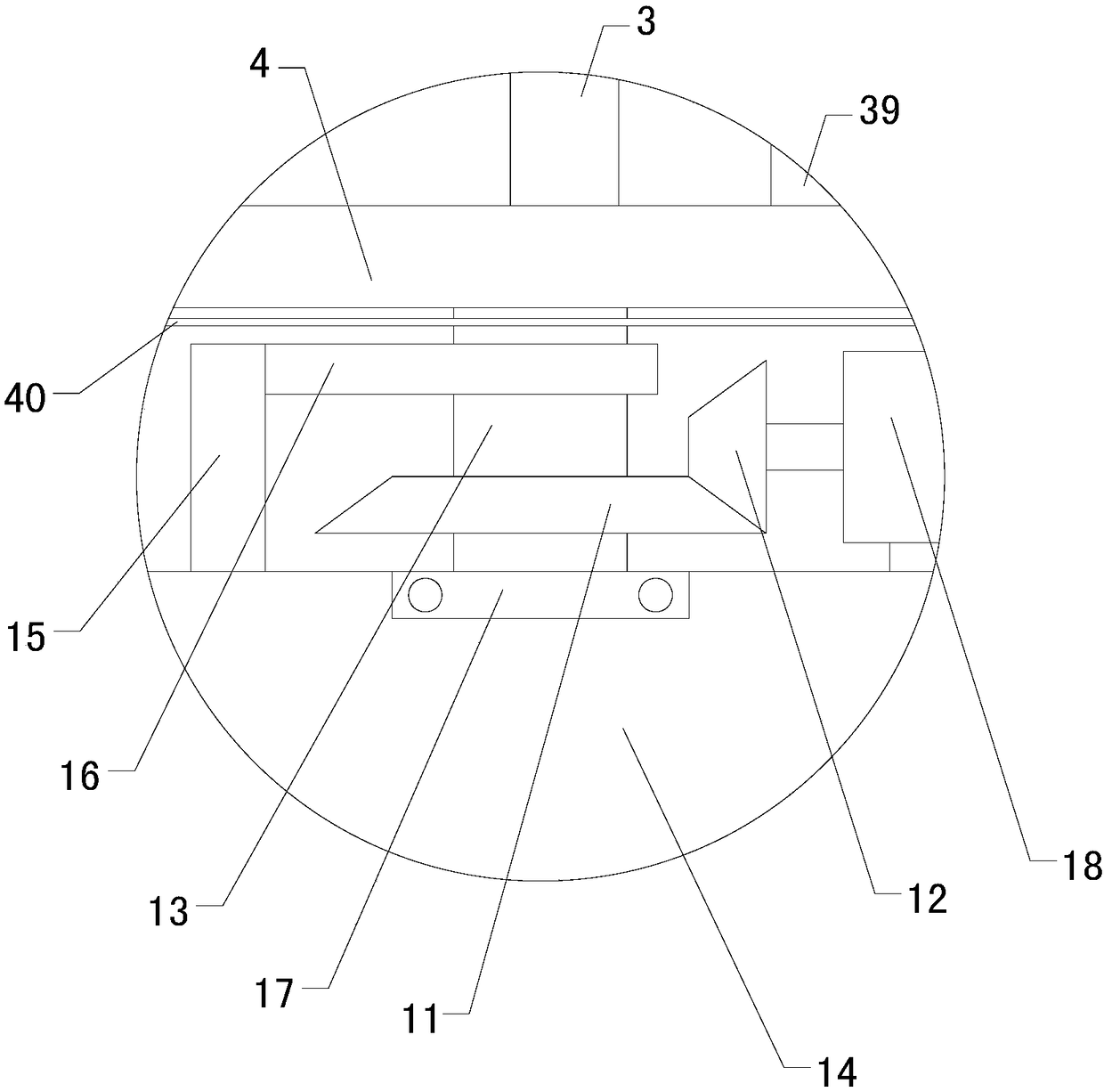
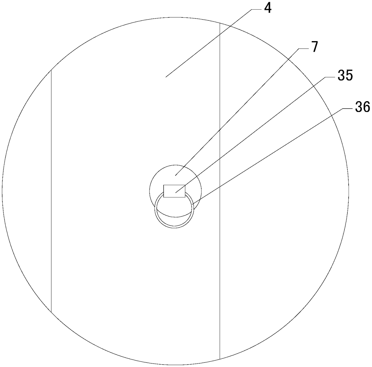
[0023] Such as Figure 1 to Figure 8As shown, a surveillance camera with patrol function of the present invention includes a camera body 1, a support ring 2 and a support rod 3, the camera body 1 is installed inside the support ring 2, and the top end of the support rod 3 is connected to the bottom end of the support ring 2; Also includes placement box 4, filter screen 5, transparent plate 6, front baffle plate 7, front spring 8, front locking rod 9, front connecting rod 10, rear baffle plate, rear spring, rear locking rod and rear connecting rod, The inside of the placement box 4 is provided with a placement cavity, the rear side wall of the placement box 4 is connected ...


PUM


Abstract

The invention relates to the technical field of camera accessory devices, in particular to a surveillance camera with a patrol function. The surveillance camera also has a dust-proof function; the angle of the camera is convenient to adjust; the camera can reciprocate; the surveillance camera comprises a camera body, a support ring and a support bar; the surveillance camera further comprises a placement box, a filter screen, a transparent plate, a front baffle, a front spring, a front card lever, a front connecting rod, a rear baffle, a rear spring, a rear card lever and a rear connecting rod;the surveillance camera further comprises a left bevel gear, a right bevel gear, a rotating rod, a slider, a first fixing rod and a second fixing rod; the top side wall of the sliding block is provided with a first clamping groove, a lower ball bearing is arranged at the first clamping groove, the right half area of the second fixing rod is longitudinally provided with a fixing hole, and an upperball bearing is arranged at the fixing hole; the surveillance camera further comprises a left support plate, a right support plate, a sliding rod, a first reciprocating screw, a left transition rod and a right transition rod; and the lower half areas of the left support plate and the right support plate are respectively provided with a left clamping hole and a right clamping hole.

Description

technical field [0001] The invention relates to the technical field of camera attachments, in particular to a monitoring camera with a patrol function. Background technique [0002] As everyone knows, a monitoring camera is a device for video recording, broadcasting and static image capture, which has been widely used in the field of cameras; the existing monitoring camera with patrol function includes a camera body, a support ring and a support rod , the camera body is installed inside the support ring, and the top of the support rod is connected to the bottom of the support ring; when the existing monitoring camera with patrol function is used, the bottom of the support rod is fixed at a certain position, and the support rod and the support ring support the camera body Generally speaking, users often install multiple groups of camera bodies in multiple locations. This installation method is costly and has high limitations; in the use of existing surveillance cameras with p...

Claims


Application Information

Patent Timeline
IPC IPC(8): H04N5/225
CPCH04N23/50H04N23/51
Inventor 陈甲运潘纲李海金
Owner ZHUCHENG HONGYUAN SECURITY TECH CO LTD
Learn More