Obstacle avoidance pre-judging method based on speed obstacle model/collision probability density model

A speed obstacle and collision probability technology, which is applied in the field of obstacle avoidance prediction based on the speed obstacle model/collision probability density model, can solve problems such as increased computational complexity, and achieve the effect of reducing fatigue and reducing complexity

Active Publication Date: 2019-02-15
SHANGHAI UNIV OF ENG SCI
View PDF7 Cites 9 Cited by
  • Summary
  • Abstract
  • Description
  • Claims
  • Application Information

AI Technical Summary

Problems solved by technology

[0003] The existing anti-collision prediction research is mainly based on machine vision and sensor methods, so that the vehicle can safely and autonomously drive to the destination in an unknown complex environment. However, with the development of the times, commercial use is inevitable, which requires Consider the cost of sensors and

Method used


Image

  • Obstacle avoidance pre-judging method based on speed obstacle model/collision probability density model
  • Obstacle avoidance pre-judging method based on speed obstacle model/collision probability density model
  • Obstacle avoidance pre-judging method based on speed obstacle model/collision probability density model

Examples


Embodiment 1

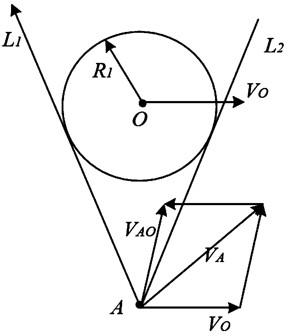
[0063] Such as figure 2 As shown, the speed obstacle model is established by the following method: set the self-vehicle as the mass point A, the obstacle vehicle is puffed into a circle O, and the radius R of the circle O 1 is the sum of the larger size of the length and width of the obstacle vehicle and the larger size of the length and width of the self-vehicle, the distance between the particle A and the circle O is the distance between the self-vehicle and the obstacle vehicle, from Point A draws two rays L 1 and L 2 , respectively circumscribed on both sides of the circle O, L 1 and L 2 The sandwiched conical surface forms a velocity obstacle cone, and the velocity vector of the self-vehicle is v A , the velocity vector of the obstacle vehicle is v O , then the relative velocity vector of the ego vehicle relative to the obstacle vehicle is v AO .

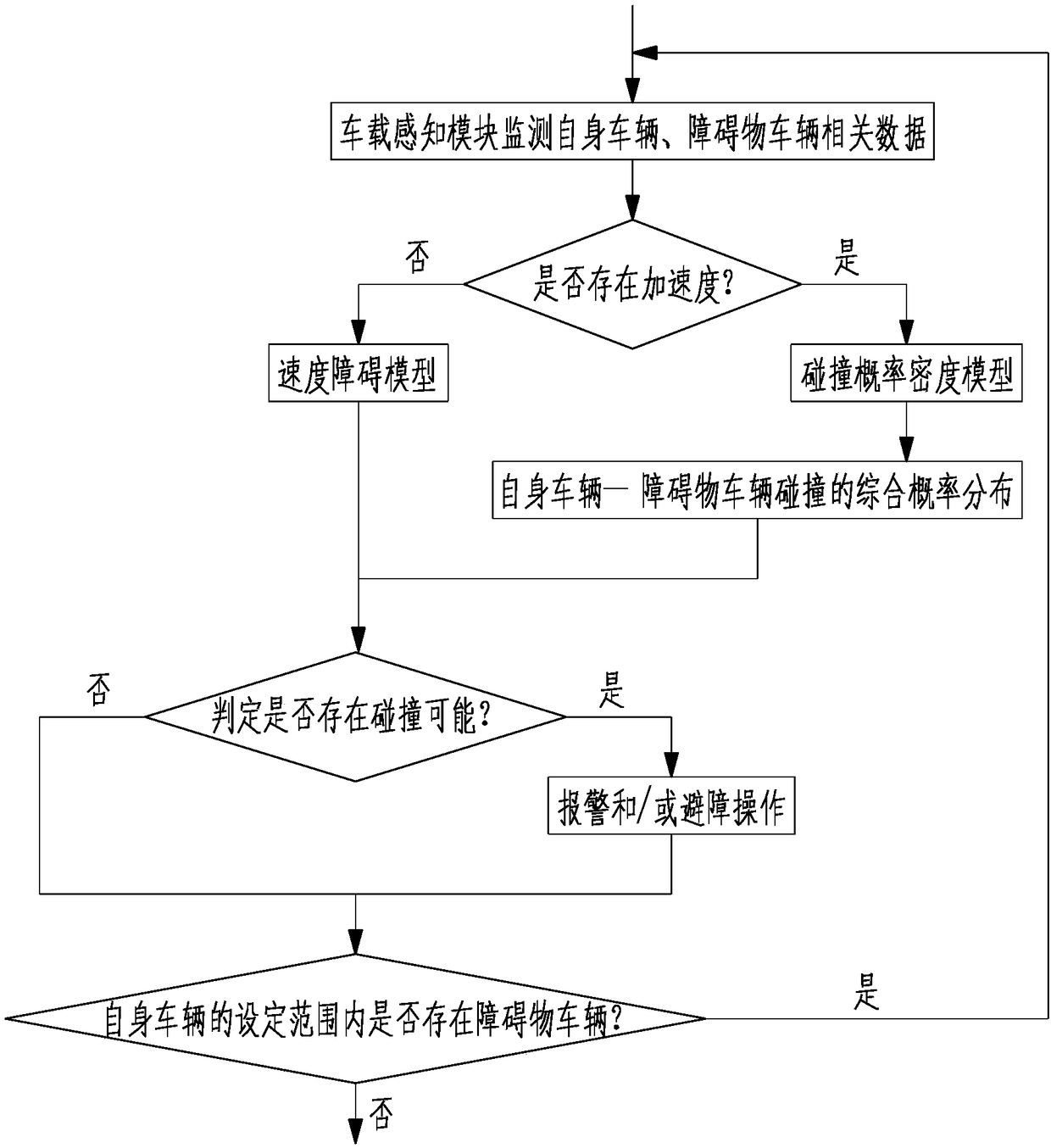
[0064] The on-board controller judges the possibility of a collision between the own vehicle and the obstacle vehicle...

Embodiment 2

[0066] Such as Figure 3-5 As shown, the collision probability density model is established by the following method:

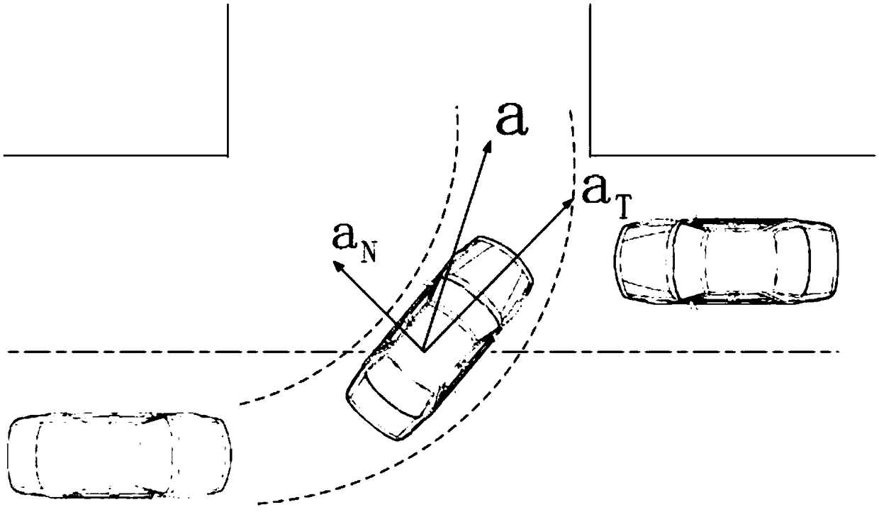
[0067] Ⅰ. Calculation of self-vehicle acceleration a: image 3 As shown, the current self-vehicle is traveling at the acceleration a, and the centripetal acceleration is a N , the tangential acceleration is a T ;

[0068] The centripetal acceleration a of the ego vehicle N The calculation formula is as follows:

[0069]

[0070] Among them: v is the current driving speed of the own vehicle, ρ(s) is the arc radius of the path trajectory of the own vehicle, both of which are obtained by the on-board controller through the on-board perception module, when ρ(s) is 0, that is, the own vehicle is currently driving in a straight line when, record as a N = 0;

[0071] The tangential acceleration of the ego vehicle a T The formula for the relationship with the rate of change of speed v is as follows:

[0072]

[0073] where: k 1 and k 2 are given const...


PUM


Abstract

The invention discloses an obstacle avoidance pre-judging method based on a speed obstacle model/collision probability density model. The obstacle avoidance pre-judging method comprises the followingsteps: S1, a vehicle-mounted sensing module of a self vehicle monitors the speed and relative position information within the set time period of the self vehicle and an obstacle vehicle in the set range by taking the self vehicle as the center and passes the speed and relative position information back to a vehicle-mounted controller; S2, the vehicle-mounted controller judges whether the self vehicle and the obstacle vehicle simultaneously move at a constant speed or not and establishes a correlation model; S3, the vehicle-mounted controller judges the collision possibility of the self vehicleand the obstacle vehicle; S4, the vehicle-mounted controller gives an alarm prompt and/or controls the self vehicle to have obstacle avoidance operation or directly goes to the step 5; and S5, the steps 1-4 are repeated until the obstacle vehicle does not exist in the set range. According to the obstacle avoidance pre-judging method, the three-dimensional realistic environment is subject to two-dimensional treatment, so that the calculating complexity level is greatly lowered; and based on intelligent driving, the degree of fatigue of a driver is greatly lowered to assist in driving.

Description

technical field [0001] The invention relates to the field of intelligent driving, in particular to an obstacle avoidance prediction method based on a speed obstacle model / collision probability density model. Background technique [0002] Vehicle anti-collision prediction is a research hotspot in the field of intelligent driving in recent years. In order to ensure the safe driving of the vehicle in a complex environment, it is not only by people to identify emergencies around the vehicle, but also by the vehicle through various sensors. Vehicles that may collide around, so as to give early warning and respond quickly, and avoid obstacles in time. [0003] The existing anti-collision prediction research is mainly based on machine vision and sensor methods, so that the vehicle can safely and autonomously drive to the destination in an unknown complex environment. However, with the development of the times, commercial use is inevitable, which requires Consider the cost of senso...

Claims


Application Information

Patent Timeline
IPC IPC(8): B60W30/095
CPCB60W30/0953B60W2520/10B60W2520/105
Inventor 陆林东张伟伟
Owner SHANGHAI UNIV OF ENG SCI
Why Eureka
Try Eureka