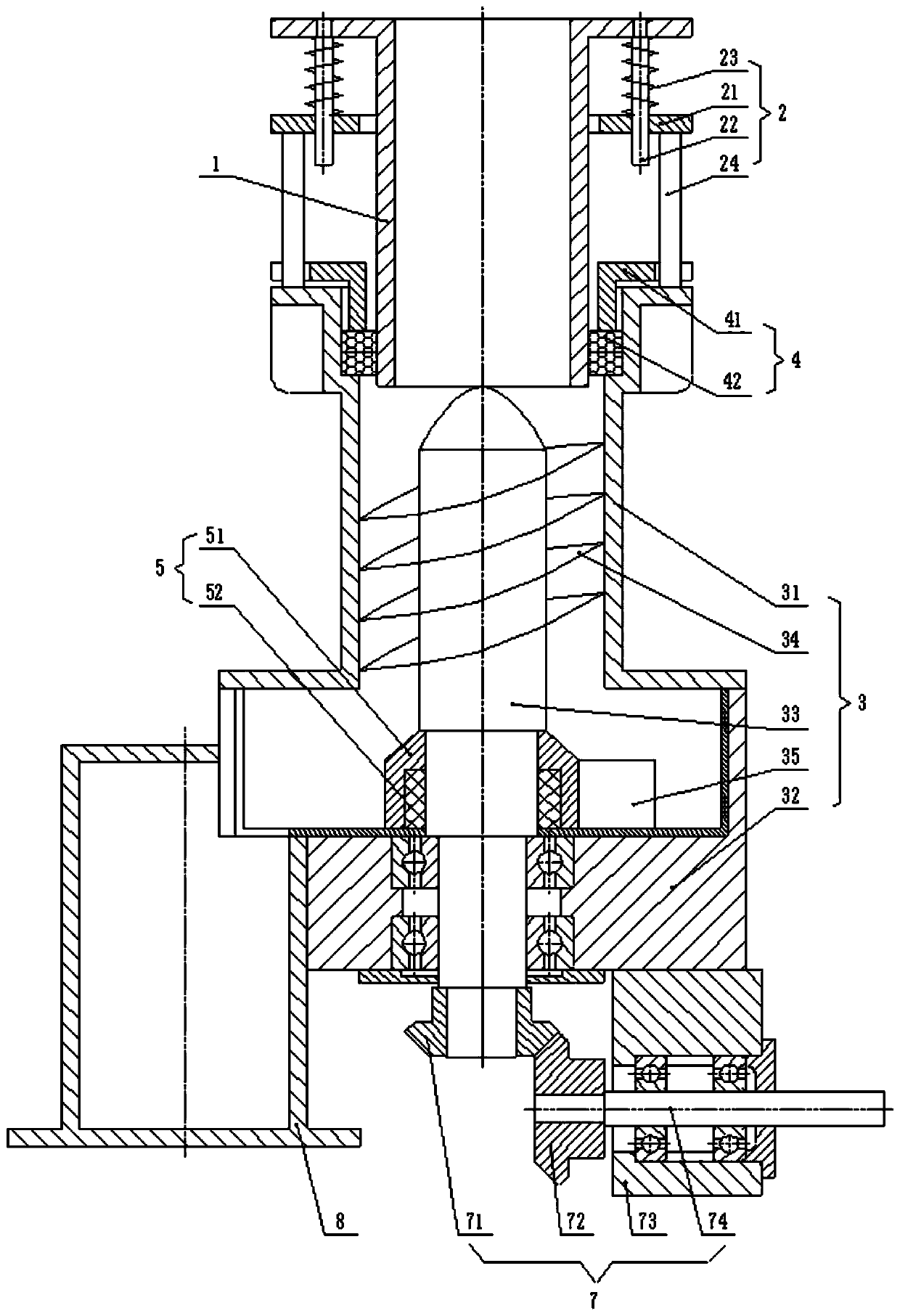
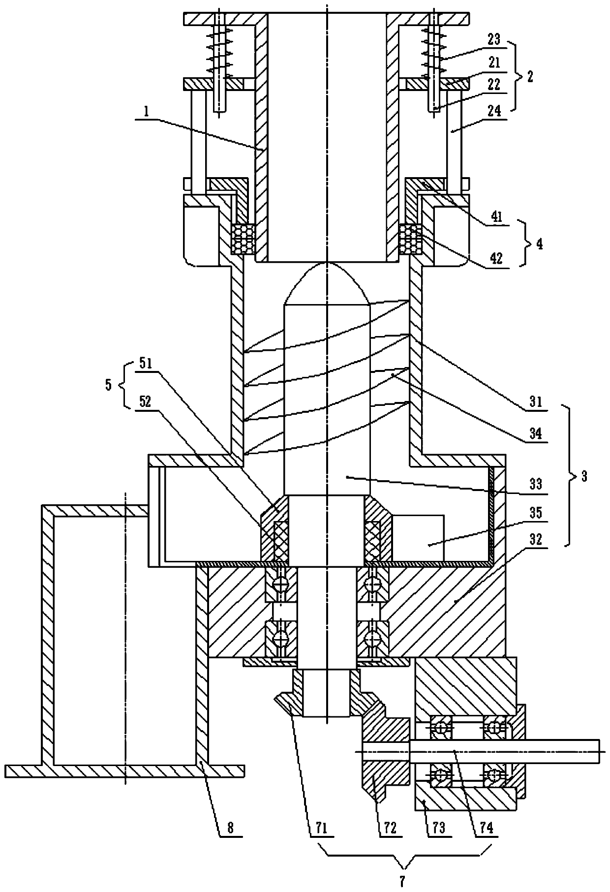
A closed unloading device

A technology of unloading device and feeding pipe, applied in the directions of transportation, packaging, loading/unloading, etc., can solve the problems of difficult industrial production, and achieve the effect of wide application, simple structure and easy operation.

Active Publication Date: 2020-05-19
海南行者新材料科技有限公司
View PDF9 Cites 0 Cited by
  • Summary
  • Abstract
  • Description
  • Claims
  • Application Information

AI Technical Summary

Problems solved by technology

In order to realize the continuous operation of materials at high temperature, it is necessary to solve the sealing problem of the material at high temperature at the inlet and outlet, especially for volatile and corrosive materials, in today's environmental protection requirements are becoming more and more High premise, if the sealing problem generated during the movement of the heating equipment cannot be solved, it will be difficult to realize its industrial production

Method used


Image

  • A closed unloading device
  • A closed unloading device

Examples


Embodiment Construction

[0022] In order to enable those skilled in the art to better understand the technical solution of the present invention, the present invention will be described in detail below in conjunction with the accompanying drawings. The description in this part is only exemplary and explanatory, and should not have any limiting effect on the protection scope of the present invention. .

[0023] It should be noted that like numerals and letters denote similar items in the following figures, therefore, once an item is defined in one figure, it does not require further definition and explanation in subsequent figures.

[0024] It should be noted that the orientation or positional relationship indicated by the terms "center", "upper", "lower", "left", "right", "vertical", "horizontal", "inner" and "outer" are Based on the orientation or positional relationship shown in the drawings, or the orientation or positional relationship that the inventive product is usually placed in use, it is onl...


PUM


Abstract

The invention discloses a sealed unloading device. The sealed unloading device comprises a feeding tube, a discharge mechanism, and an elastic connecting mechanism, wherein the feeding tube is connected with an unloading hole of a to-be-loaded device; the discharge mechanism is connected with the feeding tube through a sealing mechanism for discharging materials from the feeding tube in a sealed mode; and the elastic connecting mechanism is used for flexibly connecting the feeding tube to the discharge mechanism. According to the sealed unloading device disclosed by the invention, the sealingmechanism realizes total sealing for the unloading process, can realize totally-sealed conveying of materials, can realize conveying of working materials under a high-temperature high-pressure and corrosive environment, prevents leakage of high-temperature corrosive materials, is beneficial for environment control and surrounding environment protection, can realize transformation from a dynamic state to a static state of material conveying, and has the advantages of being wide in range of application, suitable for a bad working environment, simple in structure, easy to operate, and the like.

Description

technical field [0001] The invention relates to a discharge device, in particular to a discharge device capable of sealing discharge. Background technique [0002] At present, the most widely used material heating equipment in industrial production is mainly divided into two categories: one is static heating devices, such as various vacuum sintering furnaces, hot pressing sintering furnaces, shuttle kilns, electromagnetic induction furnaces, microwave heating furnaces etc.; the other is dynamic material heating equipment, such as rotary kiln, pusher kiln, pusher boat kiln, roller furnace, rotary heating furnace, etc. The biggest difference between the two is that the dynamic heating equipment can realize the continuous operation of materials. In order to realize the continuous operation of materials at high temperature, it is necessary to solve the sealing problem of the material at high temperature at the inlet and outlet, especially for volatile and corrosive materials, i...

Claims


Application Information

Patent Timeline
Patent Type & Authority Patents(China)
IPC IPC(8): B65G65/40B65G69/00
CPCB65G65/40B65G69/00
Inventor 欧阳晓平毛评生鲍瑞毛亮程
Owner 海南行者新材料科技有限公司
Why Eureka
Try Eureka