CNG pressure reducer for vehicle

A technology for pressure reducers and vehicles, which is applied in the direction of valve details, valve devices, valve operation/release devices, etc. It can solve the problems of poor valve stem response, small flow rate, large pressure drop, etc., and achieve flow change Small size, stable working conditions, and the effect of ensuring stability

Active Publication Date: 2021-03-23
成都恩吉威汽车技术有限公司
View PDF1 Cites 0 Cited by
  • Summary
  • Abstract
  • Description
  • Claims
  • Application Information

AI Technical Summary

Problems solved by technology

[0004] The problem with this structure is that a large slope (large flow change) will lead to large fluctuations in applications with small flow (such as idle speed), and a small slope (small flow change) will cause the valve stem to move when the flow demand is large. Poor responsiveness, resulting in high pressure drop

Method used


Image

  • CNG pressure reducer for vehicle
  • CNG pressure reducer for vehicle
  • CNG pressure reducer for vehicle

Examples


Embodiment Construction

[0024] The technical solution of the present invention will be further described in detail below in conjunction with specific examples, but the protection scope of the present invention is not limited to the following description.

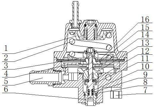
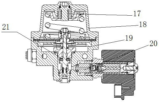
[0025] A CNG pressure reducer for a vehicle, comprising a pressure regulating spring 2, a diaphragm pressure plate 3, a valve stem 11, a valve seat 13, a diaphragm lower pressure plate 15, a pressure regulating diaphragm 16, a pressure regulating stud 17, a pressure reducing The pressure reducer cover 18 and the pressure reducer body 19, the pressure regulating spring 2 is located in the pressure reducer cover 18; the valve seat 13 is installed in the pressure reducer body 19, the valve stem 11 is suspended on the valve seat 13, and the top of the valve stem 11 is installed Pressure regulating diaphragm 16, diaphragm pressure plate 3 and diaphragm lower pressure plate 15 are respectively installed on the upper and lower sides of pressure regulating ...


PUM


Abstract

The invention relates to an automobile CNG pressure reducer which comprises a pressure adjustment spring, a diaphragm pressure plate, a valve rod, a valve seat, a diaphragm press-down plate, a pressure adjustment diaphragm, a pressure adjustment stud, a pressure reducer cover and a pressure reducer body, wherein the pressure adjustment spring is positioned in the pressure reducer cover; the valveseat is mounted in the pressure reducer body; the valve rod is mounted on the valve seat in a suspended manner; the pressure adjustment diaphragm is mounted at the top of the valve rod; the diaphragmpressure plate and the diaphragm press-down plate are correspondingly mounted on the upper and lower sides of the pressure adjustment diaphragm; the pressure adjustment diaphragm is pushed by the pressure adjustment spring to move up and down, and then the valve rod is driven to move up and down, so that a valve port can be opened and closed, and then the pressure adjustment effect can be achieved; and the valve element part of the valve rod is displayed from top to bottom as an elliptical section and enlarged gradually. By the utilization of different slope changes of the elliptical section,such a physical property that the section area changes non-linearly can be formed; and accordingly, the automobile CNG pressure reducer can be applied to different occasions.

Description

technical field [0001] The invention relates to the field of pressure reducers, in particular to a CNG pressure reducer for vehicles. Background technique [0002] At present, when clean fuels such as liquefied gas (LPG), compressed natural gas (CNG), and light hydrocarbons are used as vehicle fuels, they have the advantages of less exhaust gas, high thermal efficiency, and low price. The pressure reducer is one of the important parts of the gas system of the natural gas engine, and the performance of the pressure reducer directly affects the precise control of the engine fuel. [0003] The valve stem structure of the existing CNG pressure reducer all adopts a straight rod or inclined plane structure. The cross-sectional area of ​​this structure changes linearly, and the flow rate changes linearly with the height of the valve stem. For example, the publication number CN201351763 discloses a high pressure differential pressure reducing valve, including a valve body, a valve ...

Claims


Application Information

Patent Timeline
Patent Type & Authority Patents(China)
IPC IPC(8): F16K31/126F16K1/32
CPCF16K1/32F16K31/1262
Inventor 李波周涛陈小林苟志鹏汪洋蔚锐
Owner 成都恩吉威汽车技术有限公司
Why Eureka
Try Eureka