Fuel injection valve for combustion engine

A technology for fuel injection valves and combustion engines, which is applied in the direction of fuel injection devices, special fuel injection devices, engine components, etc., and can solve problems such as performance degradation in the combustion process, to avoid coking and deposit formation, reduce pollutant emissions or The effect of particle emissions

Inactive Publication Date: 2016-03-02
CONTINENTAL AUTOMOTIVE GMBH
View PDF4 Cites 0 Cited by
  • Summary
  • Abstract
  • Description
  • Claims
  • Application Information

AI Technical Summary

Problems solved by technology

[0005] Performance degradation of the combustion process occurs duri

Method used


Image

  • Fuel injection valve for combustion engine
  • Fuel injection valve for combustion engine
  • Fuel injection valve for combustion engine

Examples


Example Embodiment

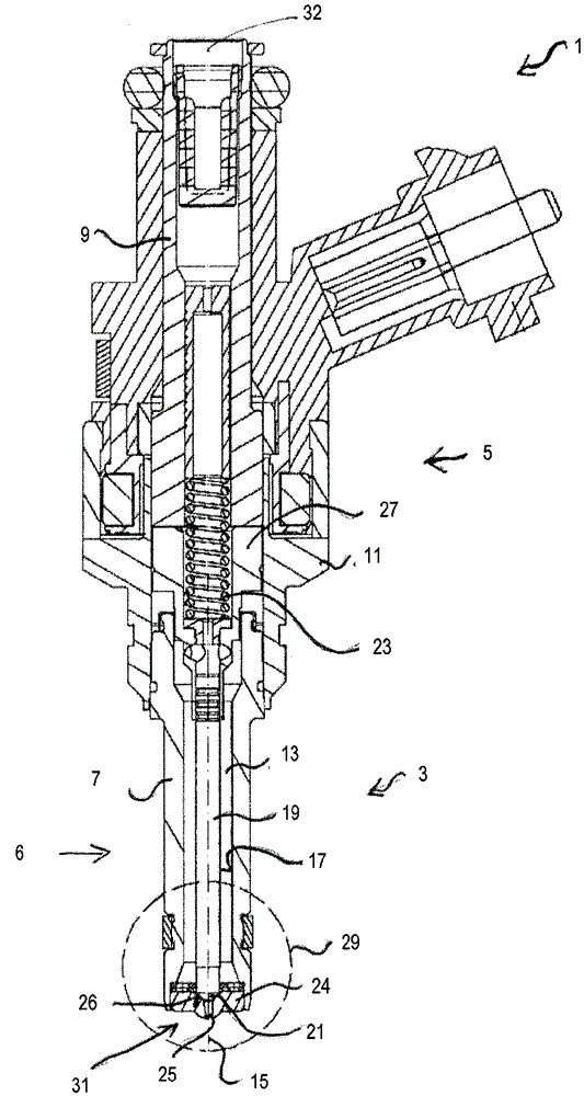
[0040] figure 1 An exemplary embodiment of an injection valve 1 with a nozzle assembly 3 and an actuator 5 is shown. The actuator 5 functionally interacts with the set of nozzle assemblies 3 .

[0041] The nozzle assembly 3 includes a valve body 6 . Injection valve 1 also includes an injector body 9 . The valve body 6 is fixedly connected to the injector body 9 , for example by means of a nozzle cap nut 11 . Other connection means like press-fit and / or welded connections are also conceivable for the fixed connection of the injector body 9 to the valve body 6 . Valve body 6 and injector body 9 form a common housing of injection valve 1 for hydraulically connecting a fuel outlet port 31 of injection valve 1 to a fuel inlet port 32 of injection valve 1 .

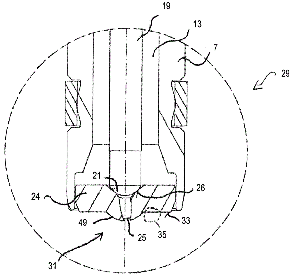
[0042] The valve body 6 has a base body 7 comprising a valve chamber 13 with a central longitudinal axis 15 and a wall 17 . Inside the valve chamber 13 , a valve needle 19 is arranged, which is included in the nozzle assem...


PUM


Abstract

A fuel injection valve (1) for a combustion engine comprises a valve body (7). The valve body (7) comprises a valve cavity (13) and a nozzle body (24). The nozzle body (24) limits a free volume of the valve cavity (13) and comprises at least one nozzle aperture (25). The nozzle body (24) comprises a surface (33) facing a combustion chamber of the combustion engine and surrounding the at least one nozzle aperture (25). The surface (33) comprises a first area (37) which completely laterally surrounds the nozzle aperture (25) and which is fluid-phobic. The surface (33) comprises a second area (39), adjacent to the first area (37) which laterally surrounds the first area (37) and has a weaker fluid-phobicity than the first area (37) or is fluid-philic.

Description

technical field [0001] The invention relates to a fuel injection valve for a combustion engine, wherein the injection valve comprises a valve body comprising a valve cavity and a nozzle body. Background technique [0002] Fuel injection valves are widely used in, inter alia, internal combustion engines, where they may be arranged for metering fluid into an intake manifold of the internal combustion engine or directly into the combustion chambers of cylinders of the internal combustion engine. [0003] Due to increasingly stringent legal regulations regarding the permissible pollutant emissions of internal combustion engines arranged, for example, in vehicles, it is necessary to take various measures in order to reduce these pollutant emissions. [0004] One possible starting point is the reduction of pollutant emissions directly produced by combustion engines. For example, soot production is highly dependent on the fuel mixture preparation in the individual cylinders of the...

Claims


Application Information

Patent Timeline
IPC IPC(8): F02M61/18F02M61/16
CPCF02M61/166F02M61/1853F02M2200/06F02M2200/9038
Inventor F.伦兹M.格兰迪S.菲利皮
Owner CONTINENTAL AUTOMOTIVE GMBH
Why Eureka
Try Eureka