Low Pressure Drop Mixer for Radial Mixing of Internal Combustion Engine Exhaust Flows, Combustor Incorporating Same, and Methods of Mixing

a technology of internal combustion engine and mixer, which is applied in the direction of machines/engines, transportation and packaging, light and heating apparatus, etc., can solve the problems of engine thermal efficiency decline, exhaust gases experiencing significant pressure drop passing through the increasingly restrictive dpf, and engine problems such as the effect of reducing the flow rate of exhaust gases, and increasing the surface area and interaction

Active Publication Date: 2009-10-15
WOODWARD GOVERNOR CO
View PDF35 Cites 135 Cited by
  • Summary
  • Abstract
  • Description
  • Claims
  • Application Information

AI Technical Summary

Benefits of technology

[0014]Embodiments of the invention provide new and improved apparatuses and method of mixing exhaust gases flowing from an internal combustion engine. The new and improved apparatuses and methods provide for low pressure drop mixing by separating an upstream flow into a plurality of segments and then rearranging the segments in a new orientation downstream. Embodiments of the new and improved methods and apparatuses adjust a temperature profile of the exhaust flow from being generally radially stratified to being angularly stratified to increase surface area and interactions between the segments of

Problems solved by technology

While such devices provide a significant environmental benefit, as with any filter, problems may occur as the DPF continues to accumulate these particulates.
After a period of time, the DPF filter substrate becomes sufficiently loaded with soot causing the exhaust gases to experience a significant pressure drop passing through the increasingly restrictive DPF.
As a result of operating with an overly restrictive DPF, the engine thermal efficiency declines due to the fact that the engine must work harder and harder simply to pump the exhaust gases through the loaded DPF.
This loss of engine performance, due to increased restriction in the exhaust system, continues to grow more severe with continued engine operation and DPF soot accumulation, eventually culminating in engine failure or engine shutdown.
Localized areas of the DPF that are warmer or cooler than the targeted regeneration temperature can decrease the effectiveness of the regeneration event.
Warmer areas may cause filter damage through thermal gradients or accelerated soot oxidation while cooler areas may result in areas of the filter that are not cleaned of soot.
Areas of the substrate that experience flows outside of the target temperature or chemical composition will degrade performance of the aftertreatment system.
Typically a DOC must operate above temperatures of approximately 350 C and an SCR system must operate above temperatures of approximately 300 C. Operation of either of these systems in temperatures lower than specified results in decreased performance and efficiency of the system.
Lean-NOx traps also have temperature limitations but further have the requirement of specific oxygen concentrations at periodic intervals.
A difficulty with these systems is that the engine exhaust may not be of sufficient temperature or composition at all times to maintain operation of these devices.
However, as previously mentioned, the DOC has its own temperature limitations and heat addition may be required prior to the DOC to insure proper operation.
The challenge when using a fuel-fired burner to perform this heat addition is to create a combustor that will raise the temperature of exhaust gasses while meeting

Method used


Image

  • Low Pressure Drop Mixer for Radial Mixing of Internal Combustion Engine Exhaust Flows, Combustor Incorporating Same, and Methods of Mixing
  • Low Pressure Drop Mixer for Radial Mixing of Internal Combustion Engine Exhaust Flows, Combustor Incorporating Same, and Methods of Mixing
  • Low Pressure Drop Mixer for Radial Mixing of Internal Combustion Engine Exhaust Flows, Combustor Incorporating Same, and Methods of Mixing

Examples


Embodiment Construction

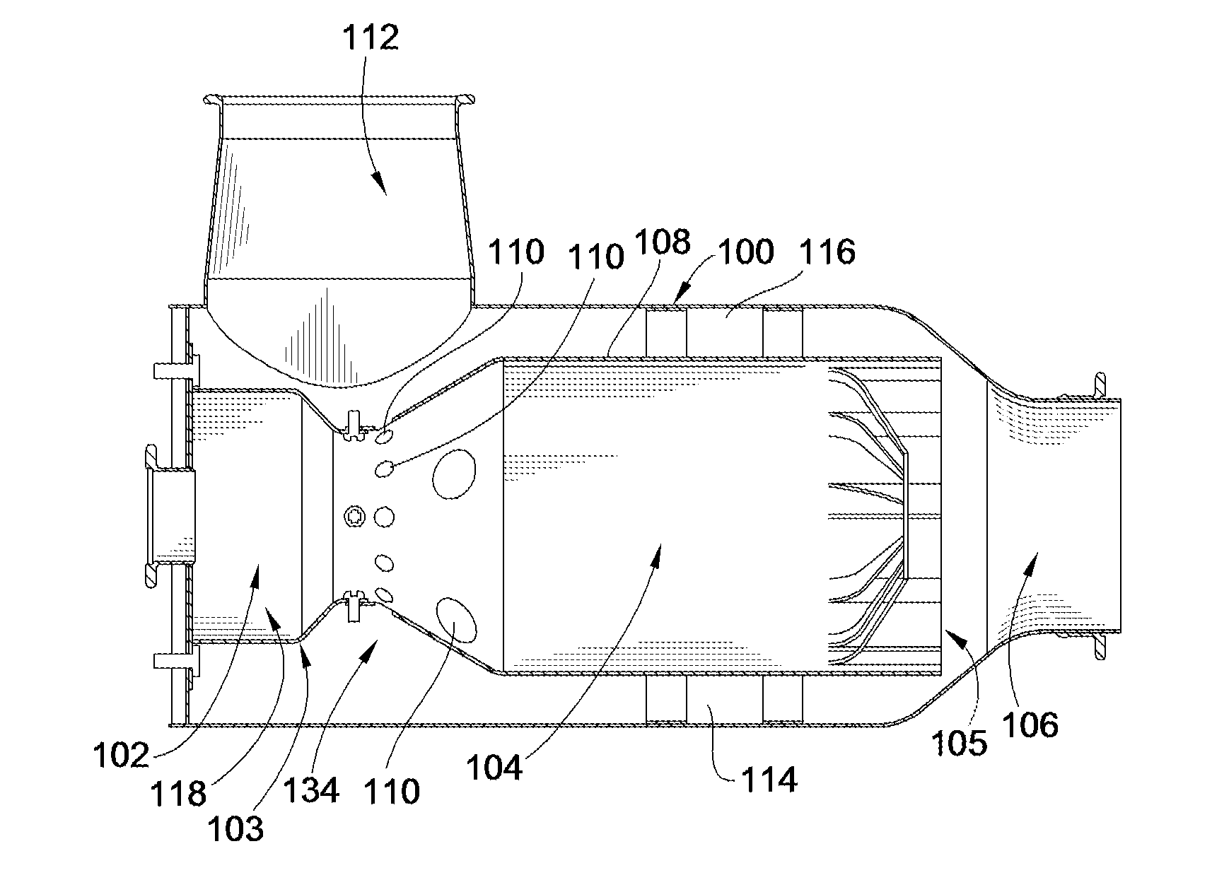
[0046]As briefly discussed above and as a matter of context for the discussion of embodiments of the present invention, a DPF is installed in the exhaust flow path of a diesel engine before or upstream of an exhaust outlet to filter out particulates from the diesel engine exhaust. In order to clean the collected particulates, e.g. soot, off of the DPF, a combustor may be used upstream of the DPF but downstream from the exhaust inlet from the engine. The engine exhaust gases flow through openings of the combustor and through the DPF before exiting into the environment via the exhaust outlet.

[0047]In a typical fuel fired combustor fuel and air are supplied via a fuel valve and an air valve, e.g. such as electrically controlled solenoid valves. The fuel and air mixture is then ignited by one or more spark plugs positioned therein. An ignition controller may be able to communicate with the engine management system (EMS), and may receive various engine and system operating parameters, su...


PUM

PropertyMeasurementUnit
Angleaaaaaaaaaa
Angleaaaaaaaaaa
Angleaaaaaaaaaa

Abstract

An exhaust aftertreatment system is provided. The exhaust aftertreatment system includes a mixing arrangement for mixing flows of exhaust along a flow path. The mixing arrangement radially and angularly rearranges segments of two different portions of flow to mix the different portions of flow. The mixing arrangement initially converts a generally radially stratified temperature profile into an angularly stratified temperature profile to increase surface area between cool segments of exhaust gas and hot segments of exhaust gas. The aftertreatment system may also include a combustion chamber, a combustor housing and a combustor liner. The mixing arrangement is downstream from the combustion chamber to direct radially outward hot gas passing through the combustor liner and to direct radially outer cool gas passing between the liner and the combustor housing radially inward in an interleaving fashion.

Description

CROSS-REFERENCE TO RELATED PATENT APPLICATION[0001]This patent application claims the benefit of U.S. Provisional Patent Application No. 61 / 043,533, filed Apr. 9, 2008, the entire teachings and disclosure of which are incorporated herein by reference thereto.FIELD OF THE INVENTION[0002]This invention generally relates to diesel engine exhaust systems and more particularly mixers for aftertreatment devices for diesel engine exhaust systems.BACKGROUND OF THE INVENTION[0003]Increasing environmental restrictions and regulations are causing diesel engine manufacturers and packagers to develop technologies that improve and reduce the impact that operation of such engines have on the environment. As a result, much design work has gone into the controls that operate the combustion process within the engine itself in an attempt to increase fuel economy and reduce emissions such as NOx and particulates. However, given the operating variables and parameters over which a diesel engine operates ...

Claims


Application Information

Patent Timeline
IPC IPC(8): F01N3/00F02C7/00F01N13/08
CPCB01F3/02B01F5/061B01F5/0616B01F2005/0634F01N3/025F01N2240/14F01N3/2892F01N2240/20F01N2470/08F01N2470/18Y02T10/26F01N3/2033Y02T10/12B01F23/10B01F25/4315B01F25/431952B01F25/431
Inventor PATERSON, CLARKMASTBERGEN, DAN B.
Owner WOODWARD GOVERNOR CO
Why Eureka
Try Eureka