Apparatus and process for production of high purity hydrogen

a technology of high purity hydrogen and process, which is applied in the direction of metal/metal-oxide/metal-hydroxide catalyst, indirect carbon-dioxide mitigation, chemical production, etc., can solve the problems of high cost, large steam reforming reactors, and high equipment cost, so as to achieve the effect of high purity and enhanced oil recovery

Inactive Publication Date: 2006-11-09
SHELL OIL CO
View PDF12 Cites 126 Cited by
  • Summary
  • Abstract
  • Description
  • Claims
  • Application Information

AI Technical Summary

Benefits of technology

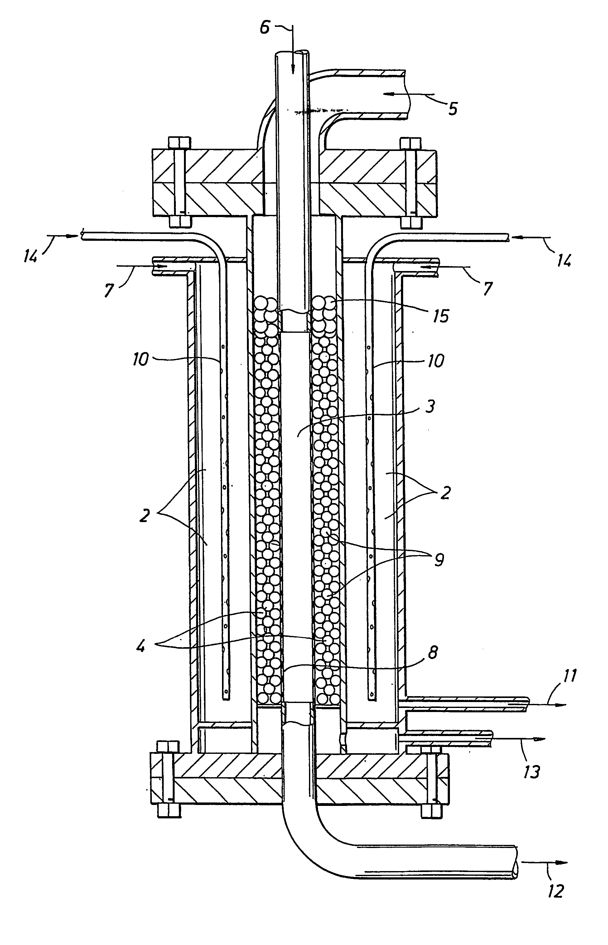
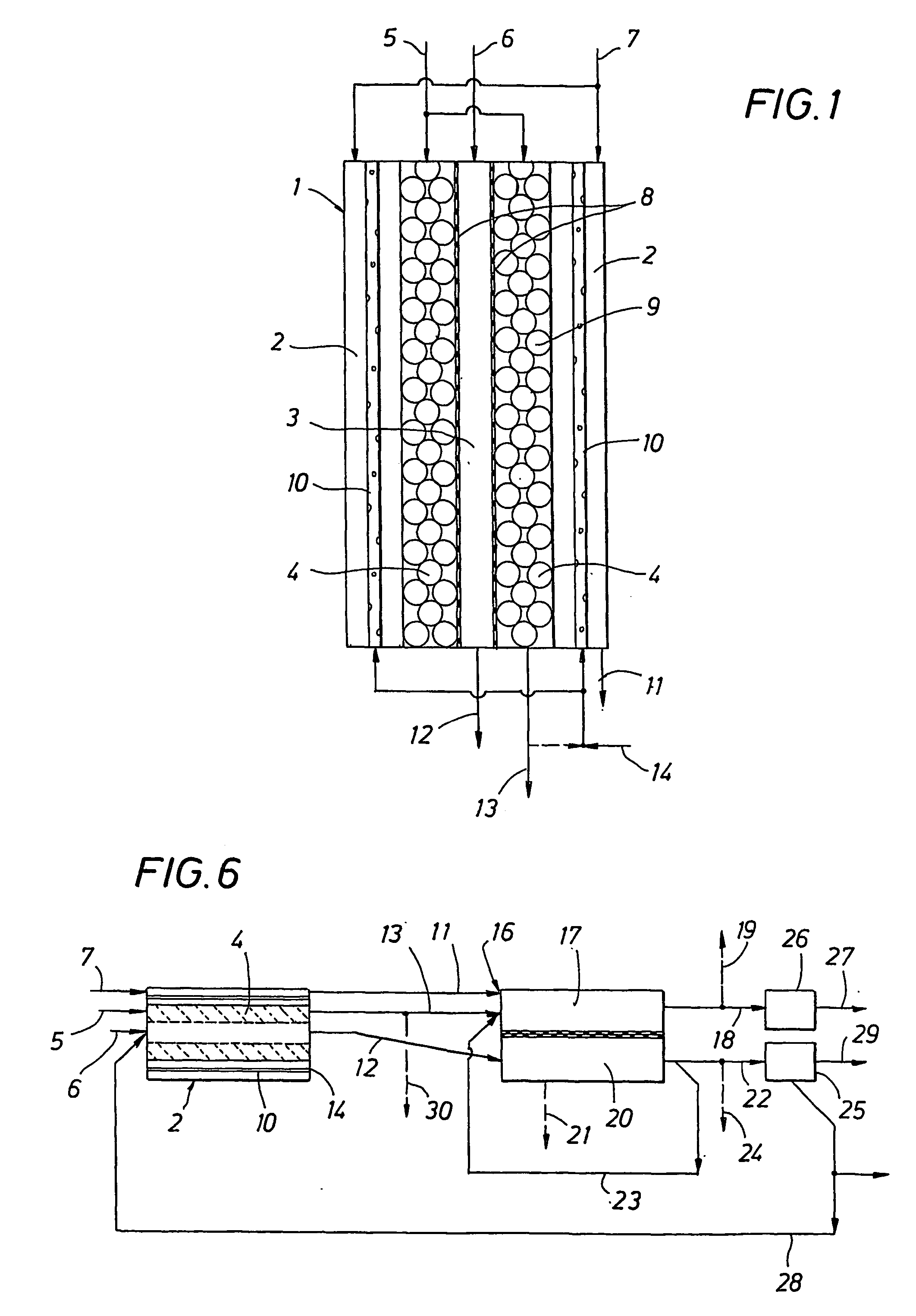
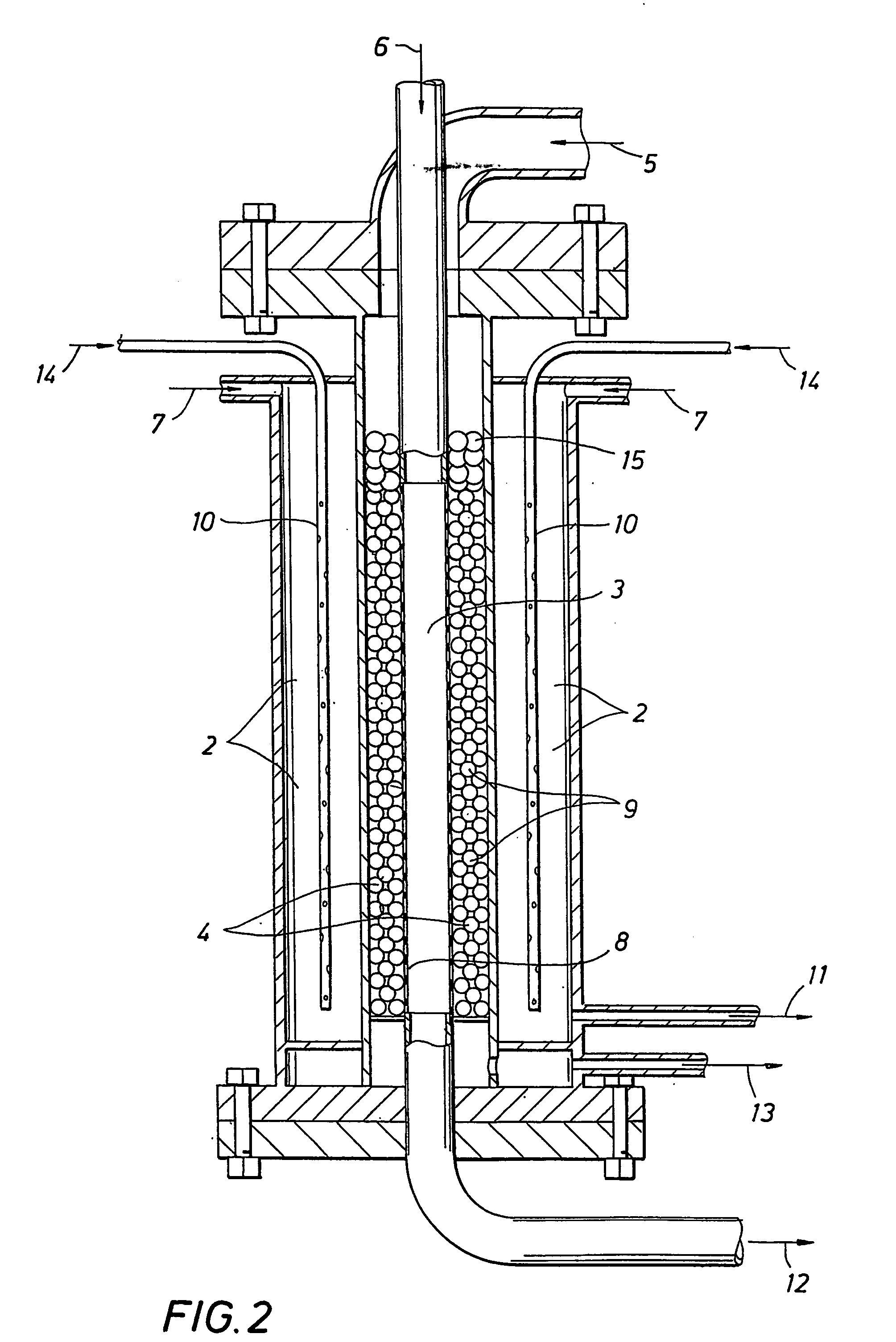
[0006] The invention relates to an improved process and apparatus for the production of high purity hydrogen by steam reforming. The apparatus is an integrated flameless distributed combustion-membrane steam reforming (FDC-MSR) reactor for steam reforming of a vaporizable hydrocarbon to produce H2 and CO2, with minimal CO as end product, and minimal concentration of CO in the H2 stream. The reactor may contain multiple flameless distributed combustion chambers and multiple hydrogen-selective, hydrogen-permeable, membrane tubes. The feed and reaction gases may flow through the reactor either radially or axially.

Problems solved by technology

Hydrogen production is commercially proven, but expensive.
The high temperature causes severe corrosion and stress problems on the equipment.
Steam reforming reactors are generally large to accomplish economies of scale.
In addition, the typical operation of the shift reactor at a lower tempe

Method used


Image

  • Apparatus and process for production of high purity hydrogen
  • Apparatus and process for production of high purity hydrogen
  • Apparatus and process for production of high purity hydrogen

Examples


embodiment 1

ILLUSTRATIVE EMBODIMENT 1

[0110]FIG. 8 shows a schematic diagram of a multi-tubular, FDC heated, radial flow, membrane, steam reforming reactor in accordance with the present invention. In the reactor shown in FIG. 8, a vaporizable hydrocarbon and steam enter the reactor at inlet 69 and flow through the reforming catalyst bed 70 (which is in the form of an annulus) containing multiple membrane tubes 71 and multiple FDC tubes 72 surrounded by the catalyst bed. In this embodiment the feed gases and reaction gases flow through the catalyst bed radially from outside to inside. The multiple hydrogen-selective, hydrogen-permeable, membrane tubes 71 are disposed axially in concentric rows in the reforming catalyst bed and serve to remove hydrogen, which is produced by the reforming reactions. The multiple FDC tubes (i.e., chambers) 72 are also disposed axially in concentric rows in the reforming catalyst bed (for example, in a ratio of 1:2 or other number of FDC tubes to the number of membr...

embodiment 2

ILLUSTRATIVE EMBODIMENT 2

[0113]FIG. 9 is a top cross-section view of the shell of the multi-tubular, FDC heated, radial flow, membrane, steam reforming reactor of FIG. 8. The cross sectional view of the reactor shows multiple membrane tubes 71 and multiple FDC tubes 72 dispersed in catalyst bed 70 with optional hollow tube or cylinder 75 being in the center of the reactor. In the example shown, the membrane tubes 71 have outside diameters (OD) of about one inch while FDC tubes have an OD of approximately two inches, although other sizes of these tubes can be suitably employed. If a sweep gas is employed, the membrane tubes 71 may contain an outer sweep gas feed tube and an inner return tube for sweep gas and hydrogen as shown in FIGS. 12 and 14. A larger shell containing more tubes duplicating this pattern can also be used.

embodiment 3

ILLUSTRATIVE EMBODIMENT 3

[0114]FIGS. 10A and 10B are schematic diagrams showing an example of a “closed ended” and of an “open ended” FDC tubular chamber which are used to drive the reforming reactions in various embodiments of the present invention. Referring to FIG. 10A, an oxidant (in this case preheated air) enters the FDC tube at inlet 76 and mixes with fuel which enters the FDC tube at inlet 77 and passes into fuel conduit 78 through nozzles 79 spaced along the length of the fuel conduit, whereupon it mixes with the air which has been preheated to a temperature such that the temperature of the resulting mixture of fuel and air is above the autoignition temperature of the mixture. The reaction of the fuel passing through the nozzles and mixing with the flowing preheated air at a temperature above the autoignition temperature of the mixture, results in flameless distributed combustion which releases controlled heat along the length of the FDC tube as shown, with no flames or hot...


PUM

PropertyMeasurementUnit
Temperatureaaaaaaaaaa
Fractionaaaaaaaaaa

Abstract

The invention relates to a new and improved process and apparatus for the production of high purity hydrogen by steam reforming. The apparatus is an integrated flameless distributed combustion-membrane steam reforming (FDC-MSR) or reactor for steam reforming of a vaporizable hydrocarbon to produce H2 and CO2, with minimal CO, and minimal CO in the H2 stream. The flameless distributed combustion drives the steam reforming reaction which pro-vides great improvements in heat exchange efficiency and load following capabilities. The reactor may contain multiple flameless distributed combustion chambers and multiple hydrogen-selective, hydrogen-permeable, membrane tubes. The feed and reaction gases may flow through the reactor either radially or axially. A further embodiment of the invention involves producing high purity hydrogen by dehydrogenation using an integrated FDC-membrane de-hydrogenation reactor. A still further embodiment of the invention involves a zero emission hybrid power system wherein the produced hydrogen is used to power a high-pressure internally manifolded molten carbonate fuel cell. In addition, the design of the FDC-SMR powered fuel cell makes it possible to capture good concentrations of CO2 for sequestration or use in other processes.

Description

FIELD OF THE INVENTION [0001] This invention relates to a process and apparatus for the production of high purity hydrogen by steam reforming, to the separation of hydrogen produced therefrom, and to the use of the hydrogen in a zero emission hybrid power system incorporating a fuel cell. BACKGROUND OF THE INVENTION [0002] The production of electrical power in the most efficient manner with minimization of waste is the focus of much research. It would be desirable to improve efficiency in the production of electricity, separate and use by-product CO2 in other processes, and produce minimal NOx. The wide availability of natural gas with the highest H:C ratio (4:1) of any fossil fuel makes it a prime candidate for electricity production with minimum CO2 emissions. [0003] Electricity can be produced in fuel cells using pure hydrogen. Hydrogen production is commercially proven, but expensive. One method of producing hydrogen is steam methane reforming where hydrocarbons and water are re...

Claims


Application Information

Patent Timeline
IPC IPC(8): B01J8/00B01B1/00B01J8/02B01J8/06C01B3/38C01B3/50C01B32/50C07C5/333H01M8/06
CPCB01B1/005B01D53/22Y02E60/50B01D63/06B01D2257/108B01D2313/22B01D2313/42B01J8/009B01J8/0214B01J8/0257B01J8/0278B01J8/0285B01J8/062B01J8/065B01J19/2475B01J23/755B01J35/065B01J2208/00212B01J2208/00309B01J2208/00495B01J2208/00504B01J2208/0053B01J2219/00006B01J2219/00265C01B3/384C01B3/501C01B31/20C01B2203/0233C01B2203/0283C01B2203/041C01B2203/047C01B2203/0475C01B2203/0811C01B2203/1247C01B2203/86C07C5/3337F23C2900/99001H01M8/0612H01M8/0618H01M8/0631H01M8/0662Y02E20/342C07C15/46C01B32/50F23C3/002Y02E20/34Y02P20/10Y02P20/151Y02P20/50Y02P20/52Y02P30/00
Inventor MIGLIN, MARIA THERESECLOMBURG, LLOYD ANTHONY JR.ELLIOTT, GLENN WILLIAMGROENEVELD, MICHIEL JANJEAN, RONG-HERMATZAKOS, ANDREAS NICHOLASMUNSHI, ABDUL WAHIDVEENSTRA, PETERWELLINGTON, SCOTT LEE
Owner SHELL OIL CO
Why Eureka
Try Eureka