Method for leveling end surface of probe of three-coordinate measuring device based on point diffraction interferometer

A technology of three-coordinate measurement and point diffraction interference, which is applied in the field of point-diffraction interference three-coordinate measurement device probe end face leveling, can solve problems such as difficult leveling and affecting measurement accuracy, meet the solution requirements, and achieve fast three-dimensional coordinate reconstruction results and precise effects

Active Publication Date: 2019-02-15
CHINA JILIANG UNIV +1
View PDF7 Cites 6 Cited by
  • Summary
  • Abstract
  • Description
  • Claims
  • Application Information

AI Technical Summary

Problems solved by technology

[0003] In order to solve the technical problem that it is difficult to level the probe end face relative to the CCD detection surface in the three-dimensional coordinate measurement method based on point diffraction interference in the prior art, which affects the measurement accuracy, the present invention provides a method for leveling the probe end face of a point diffraction interference three-dimensional coordinate measuring device , effectively eliminate the influence of the probe processing error of the point diffraction interference three-coordinate measuring device on the actual probe leveling

Method used


Image

  • Method for leveling end surface of probe of three-coordinate measuring device based on point diffraction interferometer
  • Method for leveling end surface of probe of three-coordinate measuring device based on point diffraction interferometer
  • Method for leveling end surface of probe of three-coordinate measuring device based on point diffraction interferometer

Examples


Embodiment 1

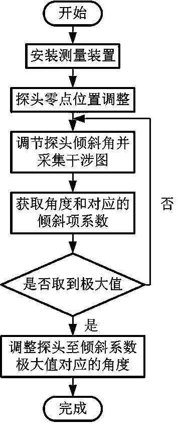
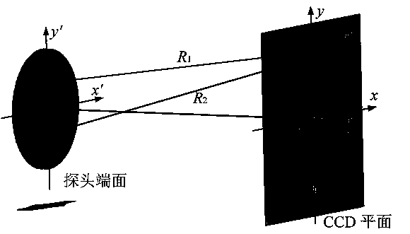
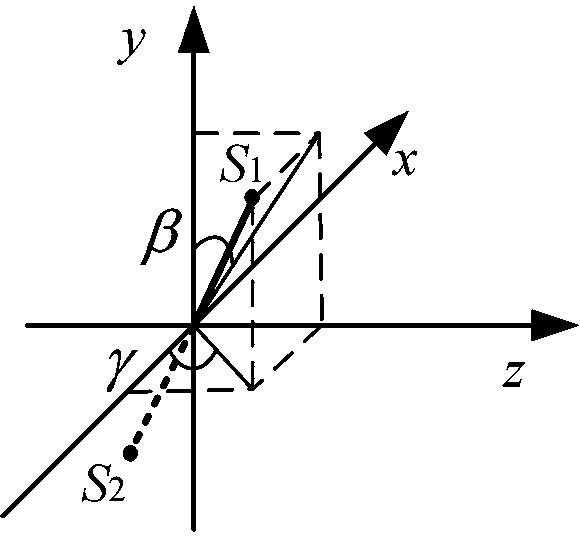
[0029] like Figure 1-7 A method for leveling the probe end face of a point-diffraction interference three-coordinate measuring device is shown. Including a three-coordinate measuring device, a CCD detector, a two-dimensional tilt adjustment frame, and a three-dimensional translation guide rail. The probe of the three-coordinate measuring device is composed of the combined installation of two optical fiber exit faces. The probe is installed on the two-dimensional tilt adjustment frame, and the probe and the two-dimensional adjustment frame are integrally installed on the three-dimensional translation guide rail. The outgoing ends of the two optical fibers are the end faces of the probe. The end face of the probe faces the CCD detector. The CCD detector does not have an imaging lens. Adopting the method of the present invention is that the measurement probe in the point diffraction interference three-dimensional coordinate measurement of 45 ° is carried out the adjustment o...


PUM


Abstract

The invention provides a method for leveling the end surface of a probe of a three-coordinate measuring device based on the point diffraction interferometer, and relates to the technical field of measurement. The method for adjusting zero position of the probe based on the wave surface symmetry is adopted. The method comprises the following steps of: acquiring the initial wave surface data by a detector; rotating the probe by 180 degree, and panning the probe to acquire the wave surface again; making the difference with the initial wave surface data after rotating the wave surface data by 180degree; panning the probe to the middle position, which is the zero position of the probe, between the initial position and the position in which the difference is the minimum value, and adjusting thetilt angle of the probe and obtaining the wave surface data; and fitting the wave surface by using the Zernike polynomial fitting method to obtain a x-y direction tilt term coefficient, and adjustingthe angle to which the coefficient is the maximum value to achieve leveling the end surface of the probe. According to the method for leveling the end surface of the probe of the three-coordinate measuring device based on the point diffraction interferometer, the technical problem of the measurement accuracy is affected in the prior art because the end face of the probe is difficult to level withrespect to the detecting surface. The beneficial effect of the invention is as follows: the state of the end face of the probe is determined, and the requirements for solving a measurement model is satisfied, so that the reconstruction result of the three-dimensional coordinate is more accurate and can be obtained more quickly.

Description

technical field [0001] The invention relates to the field of measurement technology, in particular to a method for leveling the probe end face of a point diffraction interference three-coordinate measuring device. Background technique [0002] With the continuous development of the modern machinery industry, the demand for three-dimensional coordinate measurement technology is also increasing. At present, the main three-dimensional coordinate measuring instruments include three-dimensional coordinate measuring machines and laser trackers. Among them, the three-dimensional coordinate measuring machine is widely used in reverse engineering, etc., but its structure is complex and expensive. When performing three-dimensional coordinate measurement in a large space, a huge measurement platform is required, and its expensive cost limits its application. Laser trackers have limited applications due to their measurement accuracy. In recent years, with the continuous development of...

Claims


Application Information

Patent Timeline
Patent Type & Authority Applications(China)
IPC IPC(8): G01B11/00
CPCG01B11/002
Inventor 王道档解钟敏孔明雷李华赵军许新科刘维郭天太曾燕华
Owner CHINA JILIANG UNIV
Why Eureka
Try Eureka