A LED constant current drive circuit with high pf and no flicker

A constant current drive, no flicker technology, applied in the direction of electric light source, electrical components, electroluminescent light source, etc., can solve the problems of LED load current ripple, large ripple, PF difference, etc., to reduce the ripple The effect of current

Active Publication Date: 2021-09-07
上海源微电子科技有限公司
View PDF0 Cites 0 Cited by
  • Summary
  • Abstract
  • Description
  • Claims
  • Application Information

AI Technical Summary

Problems solved by technology

[0004] In the mains power supply system, the AC input is 220V / 50HZ alternating current, and after rectification and filtering, it becomes a steamed bun wave with a peak value of 310V / 100HZ. If the filter capacitor C is large enough to filter out the AC ripple, then the LED load There will be no ripple in the output current, but the PF of the capacitor will become very poor if it is used in a large input.
If the filter capacitor is small, although the PF will be high, the ripple after rectification will be relatively large, and the current ripple output by the LED load will also be large

Method used


Image

  • A LED constant current drive circuit with high pf and no flicker
  • A LED constant current drive circuit with high pf and no flicker
  • A LED constant current drive circuit with high pf and no flicker

Examples


Embodiment 1

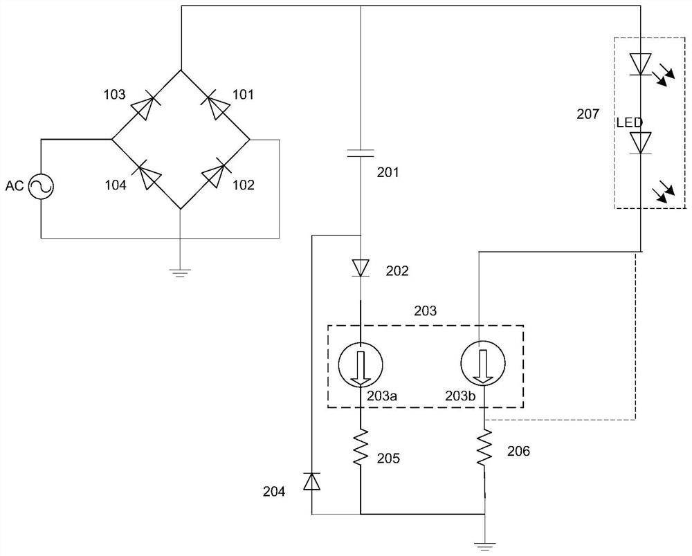
[0040] image 3 It is the LED constant current drive circuit diagram with high PF and no flicker of the first embodiment.

[0041] Such as image 3 As shown, in this embodiment, the LED constant current drive circuit with high PF and no flickering includes: including: input rectifier bridge, LED light string 207, energy storage capacitor 201, constant current control unit 203, first diode 202 , the first feedback resistor 205 , the second feedback resistor 206 and the second diode 204 .

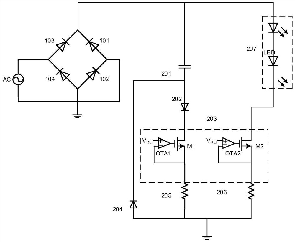
[0042] The constant current control unit 203 includes: a first constant current source and a second constant current source. In this embodiment, the first constant current source includes: a MOS transistor M1 and an operational amplifier OTA1. The gate of the MOS transistor M1 serves as a control terminal of the first constant current source, and the source of the MOS transistor M1 serves as the other control terminal of the first constant current source. The second constant current source ...

Embodiment 2

[0051] Figure 4 It is the LED constant current drive circuit diagram with high PF and no flicker of the second embodiment.

[0052] Such as Figure 4 As shown, in this embodiment, the LED constant current drive circuit with high PF and no flickering includes: including: input rectifier bridge, LED light string 207, energy storage capacitor 201, constant current control unit 203, first diode 202 , the first feedback resistor 205, the second feedback resistor 206, the second diode 204, the inductor 209A and the third diode 208B.

[0053] The constant current control unit 203 includes: a first constant current source and a second constant current source. In this embodiment, the first constant current source includes: a MOS transistor M1 and an operational amplifier OTA1. The drain of the MOS transistor M1 serves as a control terminal of the first constant current source, and the source of the MOS transistor M1 serves as the other control terminal of the first constant current...

Embodiment 3

[0062] Figure 5 It is the LED constant current drive circuit diagram with high PF and no flicker of the third embodiment.

[0063] Such as Figure 5 As shown, in this embodiment, the LED constant current drive circuit with high PF and no flickering includes: including: input rectifier bridge, LED light string 207, energy storage capacitor 201, constant current control unit 203, first diode 202 , the first feedback resistor 205, the second feedback resistor 206, the second diode 204, the transformer 209B, the third diode 208B and the first capacitor 210B.

[0064] The constant current control unit 203 includes: a first constant current source and a second constant current source. In this embodiment, the first constant current source includes: a MOS transistor M1 and an operational amplifier OTA1. The drain of the MOS transistor M1 serves as a control terminal of the first constant current source, and the source of the MOS transistor M1 serves as the other control terminal o...


PUM


Abstract

The present invention provides a LED constant current drive circuit with high PF and no flickering. The two input ends of the input rectifier bridge are connected to the input alternating current; one end of the energy storage capacitor is connected to an output end of the input rectifier bridge, and the other end is respectively connected to the The anode of the first diode is connected to the cathode of the second diode; one control terminal of the first constant current source is connected to the cathode of the first diode; one end of the first feedback resistor is connected to the other end of the first constant current source One control end is connected, and the other end is connected with the anode of the second diode; one end of the LED light string is connected with an output end of the input rectifier bridge, and the other end is connected with any control end of the second constant current source; the second feedback One end of the resistor is connected to the other control end of the second constant current source, and the other end is connected to the anode of the second diode. Its advantage is that it adopts the scheme of controlling the charging current of the energy storage capacitor, so that the circuit can achieve high PF while reducing the ripple current of the LED load, so as to achieve the purpose of no flicker.

Description

technical field [0001] The invention relates to an LED constant current drive circuit with high PF and no flicker. Background technique [0002] figure 1 It is a traditional constant current drive circuit. [0003] Such as figure 1 As shown, the traditional constant current drive circuit is composed of rectifier diodes D1, D2, D3, D4 to form an input rectifier bridge, LED light string, detection resistor R, constant current controller U, and filter capacitor C. [0004] In the mains power supply system, the AC input is 220V / 50HZ alternating current, and after rectification and filtering, it becomes a steamed bun wave with a peak value of 310V / 100HZ. If the filter capacitor C is large enough to filter out the AC ripple, then the LED load There will be no ripple in the output current, but the PF of the capacitor will become very poor if it is used in a large input. If the filter capacitor is small, although the PF will be high, the ripple after rectification will be relati...

Claims


Application Information

Patent Timeline
Patent Type & Authority Patents(China)
IPC IPC(8): H05B45/30H05B45/345H05B45/355H05B45/36H05B44/00
CPCH05B45/37
Inventor 张义薛涛
Owner 上海源微电子科技有限公司
Why Eureka
Try Eureka