
Static gantry and pseudo-static seismic testing device

A bench and static technology, applied in the field of seismic testing, can solve the problems of lack of test jacks, etc., and achieve the effect of simple structure, strong practicability and reasonable design

Active Publication Date: 2019-02-19
CHENGDU UNIVERSITY OF TECHNOLOGY
View PDF12 Cites 11 Cited by
  • Summary
  • Abstract
  • Description
  • Claims
  • Application Information

AI Technical Summary

Problems solved by technology

[0003] However, when the existing laboratory does not meet the corresponding test equipment, such as the lack of test jacks and / or rolling guides, and in order to study the seismic performance of bending, shearing and compression test pieces with corners at the end, then how to Using the existing conditions of the laboratory, design a new bench to meet the conditions of the seismic test, and then conduct the seismic test

Method used


Image

  • Static gantry and pseudo-static seismic testing device
  • Static gantry and pseudo-static seismic testing device
  • Static gantry and pseudo-static seismic testing device

Examples


Embodiment 1

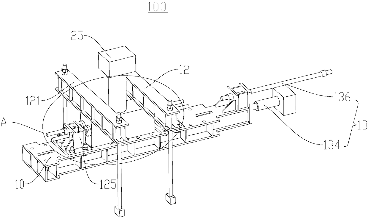
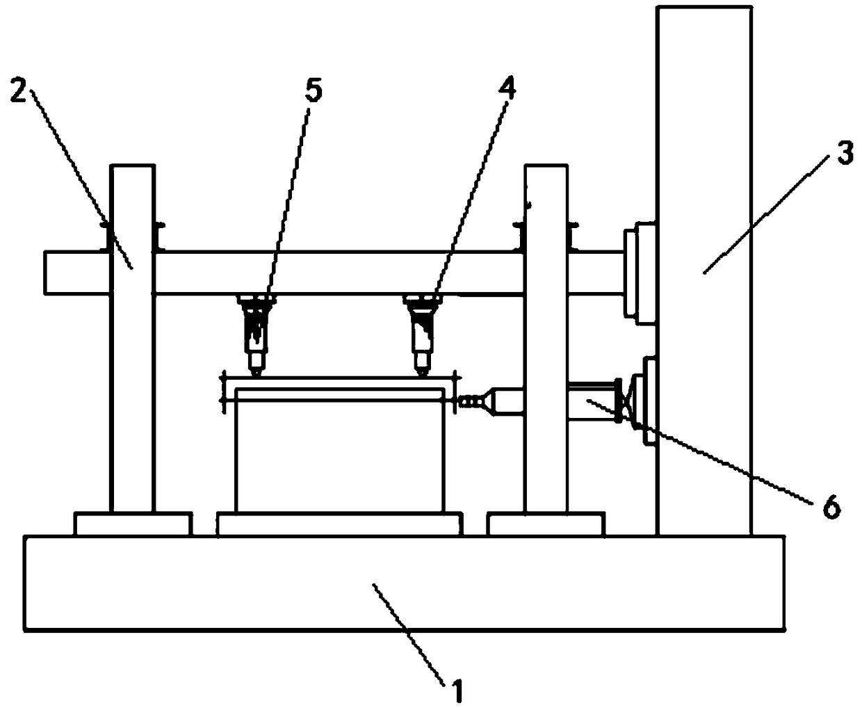
[0048] figure 1 A schematic structural diagram of the static bench 100 provided in this embodiment, figure 2 It is a schematic diagram of the existing quasi-static seismic test device, please refer to figure 1 and figure 2 shown.

[0049] The existing quasi-static seismic test device includes a static pedestal 1 , a reaction frame 2 , a reaction wall 3 , a rolling guide 4 , a jack 5 and a reciprocating actuator 6 .

[0050] However, in the specific test, due to the lack of corresponding equipment in the laboratory, such as the lack of jacks 5 and rolling guides 4, the quasi-static seismic test cannot be completed according to the existing test conditions.

[0051] In order to study the seismic performance of bending-shear-compression members (with corners at the ends), it is necessary to design and improve on the basis of existing test conditions. It is necessary for the static bench to meet the boundary conditions that can provide the specimen with embedding.

[0052] ...

Embodiment 2

[0079] Embodiment 2 of the present invention provides a quasi-static anti-seismic test device 20, including a reaction force wall 3, a reaction force loading frame 21, a first spherical joint actuator 22, a second spherical joint actuator 23, and 1 provides a static bench 100.

[0080] Figure 5 The structural representation of the quasi-static anti-seismic test device 20 provided for embodiment 2, Figure 6 For the structural schematic diagram of the counter force loading frame 21, please refer to Figure 5 and Figure 6 shown.

[0081]The reaction wall 3 is fixedly installed in the existing laboratory, and the floor 24 of the test area of ​​the existing laboratory is provided with a plurality of ground anchor holes, and the pedestal 10 of the static bench 100 is fixed through the ground anchor holes and the reaction wall 3, The pedestal 10 is fixedly connected to the reaction wall 3 through the first fixing component, and the pedestal 10 is fixedly connected to the floor...


PUM


Abstract

The invention discloses a static gantry and a pseudo-static seismic testing device, which relate to the technical field of seismic testing. The static gantry is used to fix a testing piece to a testing area having a reaction wall, and comprises a gantry base, a testing piece fixing assembly, and a gantry base fixing assembly. The gantry base comprises a base horizontal fixing portion and a testingpiece fixing portion. The base horizontal fixing portion is located at the end of the gantry base. The gantry base fixing assembly comprises a first fixing assembly which matches with the base horizontal fixing portion to fixedly connect the gantry base and the reaction wall. The testing piece fixing assembly can fix the testing piece to the testing piece fixing portion. The static gantry is reasonable in design and firm in fixing, can provide a flat field for the testing piece, and ensures the requirement of providing an embedded end for the testing piece. The static gantry can also be usedas a gantry with an expandable function, and has strong practicability.

Description

technical field [0001] The invention relates to the technical field of anti-seismic tests, in particular to a static stand and a quasi-static anti-seismic test device. Background technique [0002] The standard test conditions for quasi-static seismic tests specified in the seismic test regulations include: rolling guide rails, test jacks, reaction walls, static pedestals, and reciprocating actuators. [0003] However, when the existing laboratory does not meet the corresponding test equipment, such as the lack of test jacks and / or rolling guides, and in order to study the seismic performance of bending, shearing and compression test pieces with corners at the end, then how to Using the existing conditions of the laboratory, a new bench is designed to meet the conditions of the seismic test, and then the seismic test is carried out. Contents of the invention [0004] The purpose of the present invention is to provide a static bench, which can provide a flat site for the t...

Claims


Application Information

Patent Timeline
Patent Type & Authority Applications(China)
IPC IPC(8): G01M13/00G01M7/02
CPCG01M7/02G01M13/00
Inventor 赵华刘洋蔡国军刘志华杨佳皓
Owner CHENGDU UNIVERSITY OF TECHNOLOGY
Learn More