
Lifting frame of electric welding machine

A technology of electric welding machine and frame, which is applied in the field of lifting frame of electric welding machine, can solve problems such as heavy weight of electric welding machine, deformation of electric welding machine shell, bumpy lifting process, etc., so as to improve safety and service life, improve Good effect of stability and safety, convenience and safety

Active Publication Date: 2020-08-21
CHENGXI SHIPYARD
View PDF8 Cites 0 Cited by
  • Summary
  • Abstract
  • Description
  • Claims
  • Application Information

AI Technical Summary

Problems solved by technology

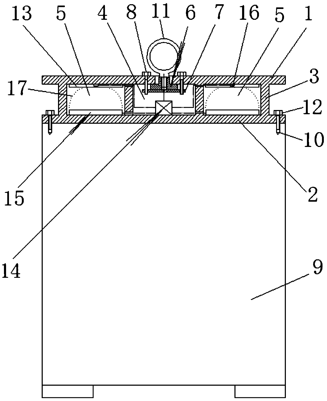
[0004] One is that the structural design of the welding machine itself is to directly connect the welding machine shell for hoisting through the lifting screw holes provided at both ends of the upper part of the welding machine (hanging ring screws are installed in the screw holes), but due to the heavy weight of the welding machine itself, and the welding machine The rigidity of the shell is relatively weak. During the process of hoisting the welding machine with a forklift, the lifting height is limited so that the wire rope cannot be too long. The deformation of the shell leads to strain and damage to the internal structure of the welding machine, leakage of electricity, and burnt parts, etc., which shortens the service life of the welding machine, affects the normal use of the welding machine, and has certain safety hazards
[0005] Second, in the process of using a forklift combined with wire ropes and other slings to lift and transport the welding machine, due to the unevenness of the road surface and the track, the lifting process is bumpy, and there is a hidden danger of the welding machine slipping, which not only damages the welding machine, but also causes potential for harm

Method used


Image

  • Lifting frame of electric welding machine

Examples


Embodiment Construction

[0032] The specific implementation manners of the present invention will be further described below in conjunction with the drawings and examples. The following examples are only used to illustrate the technical solution of the present invention more clearly, but not to limit the protection scope of the present invention.

[0033] Such as figure 1 Shown is an embodiment of a hoisting frame of an electric welding machine of the present invention, comprising an upper base plate 1, a lower base plate 2, and a number of vertical plates 3 connected between the upper base plate 1 and the lower base plate 2. An integrated rack body is formed, and the vertical plates 3 are distributed in parallel at intervals and divide the space formed between the upper base plate 1 and the lower base plate 2 into several neutral positions. Among the plurality of neutral positions, one of the neutral positions It is the center neutral gear 4, and the central neutral gear 4 is located below the centr...


PUM


Abstract

The invention relates to the technical field of lifting tools, and discloses a lifting machine frame for an electric welding machine. The lifting machine frame comprises an upper bottom plate, a lowerbottom plate and several vertical plates connected between the upper bottom plate and the lower bottom plate, wherein the vertical plates are distributed in parallel at intervals and divide a space formed between the upper bottom plate and the lower bottom plate into several neutral gears, one neutral gear is a central neutral gear, the other pair of neutral gears are shoveling conveying neutralgears, a through hole is formed in the center of the upper bottom plate, a movable central lifting block and a clamping plate used for fixing the central lifting block are sequentially arranged on theposition, located at the through hole portion, of the lower end surface of the upper bottom plate from top to bottom, the clamping plate is connected to the upper bottom plate through connecting screws, and are used for fixing the central lifting block in a clamping mode, and bolt holes which are connected with lifting screw holes in the electric welding machine are formed in the lower bottom plate. According to the lifting machine frame, lifting deformation of the electric welding machine can be effectively prevented, and the safety of the lifting operation of the electric welding machine can be improved.

Description

technical field [0001] The invention relates to the technical field of lifting tools, in particular to a lifting frame of an electric welding machine. Background technique [0002] The shipbuilding factory involves a large number of tasks such as facility maintenance, technical transformation, and equipment repair, and its scope of work involves every corner of the factory, especially in the process of maintenance and repair of electrical, pipeline, and door machines. And mobile welding machine, welding machine is an indispensable repair equipment. [0003] But there are following deficiencies in the lifting process of existing electric welding machine: [0004] One is that the structural design of the welding machine itself is to directly connect the welding machine shell for lifting through the hoisting screw holes (the lifting ring screws are installed in the screw holes) provided at both ends of the upper part of the welding machine. However, due to the heavy weight of ...

Claims


Application Information

Patent Timeline
Patent Type & Authority Patents(China)
IPC IPC(8): B66C1/10
CPCB66C1/10
Inventor 梅建强
Owner CHENGXI SHIPYARD
Learn More