Adjustable fan blades

An adjustable and deflection technology, which is applied to the components of pumping devices for elastic fluids, non-variable pumps, pump components, etc., can solve the problems of limited airflow expansion and increase expansion, and achieve structural simple effect

Active Publication Date: 2020-11-24
淮北创之社信息科技有限公司
View PDF17 Cites 0 Cited by
  • Summary
  • Abstract
  • Description
  • Claims
  • Application Information

AI Technical Summary

Problems solved by technology

[0004] The invention patent with the patent number JP2008-185111 and the invention patent with the patent number 200910254222.5 applied in China both disclose an electric fan, which is provided with a rectification device between the fan and the protective cover, and the rectification device is mainly through a rack and a gear Cooperate to deflect the rectifying wing, and change the wind direction by controlling the deflection angle of the rectifying wing, but this invention guides the airflow generated after the fan blade exhausts the wind, and then changes the wind direction, but its change in the expansion degree of the airflow is limited, and the airflow The middle position will increase its expansion after being hindered by the fairing

Method used


Image

  • Adjustable fan blades
  • Adjustable fan blades

Examples


Embodiment Construction

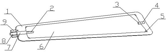
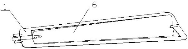
[0025] The fan blade with adjustable deflection angle of the present invention is realized in this way: the fan blade with adjustable deflection angle of the present invention consists of a blade main body (1), a driving clamp arm (2), a fixed clamp arm (3), and a fixing frame ( 4), built-in slot (5), deflection plate (6), rotary sleeve (7), drive shaft (8) and connecting plate (9), the main body plate has a built-in slot (5), the built-in The groove (5) runs through the main board, the width of the main board gradually increases from one end to the other end, the main board is made of plastic, the distance between one end of the through groove and one end of the main board is greater than the distance between the other end of the through groove and the main board The distance from the other end, the rotating sleeve (7) is placed at one end of the main plate, the rotating sleeve (7) extends along the axis of the main plate to one end of the through groove, the fixing frame (4) ...


PUM


Abstract

The invention relates to a fan blade capable of adjusting a deflection angle and discloses a fan blade for adjusting a windward angle of the fan blade through deflection adjustment of a deflection plate. The fan blade is characterized in that a main body plate is provided with a built-in groove; the built-in groove runs through the main body plate; the width of the main body plate gradually increases from one end to the other end; the main body plate is made of plastic; the distance between one end of a through groove and one end of the main body plate is larger than the distance between the other end of the through groove and the other end of the main body plate; a rotating sleeve is arranged at one end of the main body plate, and the rotating sleeve extends along the axis of the main body plate to one end of the through groove; a fixed frame is arranged at the other end of the main body plate; the deflection plate is arranged in the built-in groove, a gap is arranged between the outer side edge of the deflection plate and the groove wall of the built-in groove, four corners of the deflection plate are arc-shaped, and the width of the deflection plate is gradually increased from one end to the other end; a fixed clamping arm is arranged at the other end of the deflection plate and is rotatably connected with the fixed frame; a driving clamping arm is arranged at one end of thedeflection plate, and one end of the driving clamping arm is rotatably arranged in the rotating sleeve.

Description

technical field [0001] The invention relates to a fan blade with adjustable deflection angle, which relates to a fan blade capable of adjusting the deflection angle of the blade, and belongs to the field of ventilation equipment. In particular, it relates to a fan blade for adjusting the windward angle of the fan blade by adjusting the deflection of the deflection plate. Background technique [0002] At present, electric fans mainly use the motor shaft to drive the fan blades to rotate, and the rotation of the fan blades drives the airflow to form wind. When working, the degree of expansion of the airflow is determined by the deflection angle of the blades. Since the deflection angle of the existing blades is fixed, Therefore, the expansion degree of the airflow is also fixed, but when the required airflow velocity changes, it is realized by changing the rotation speed of the motor, but while increasing the rotation speed, the expansion degree of the airflow also changes, th...

Claims


Application Information

Patent Timeline
Patent Type & Authority Patents(China)
IPC IPC(8): F04D29/26F04D27/00
CPCF04D27/002F04D29/26
Inventor 不公告发明人
Owner 淮北创之社信息科技有限公司
Why Eureka
Try Eureka