Pipe joint structure

A technology of pipe joint and connecting seat, which is applied in the direction of pipe/pipe joint/pipe fitting, sealing surface connection, passing element, etc., which can solve the problems of weak positioning force and the inability of the pipe joint 80 to be completely sealed.

Active Publication Date: 2020-10-09
WEN SHENG FU CO LTD
View PDF4 Cites 0 Cited by
  • Summary
  • Abstract
  • Description
  • Claims
  • Application Information

AI Technical Summary

Problems solved by technology

[0003] However, the above-mentioned known structure still has the following problems in practical application: it only utilizes the snap teeth 832 of the snap ring 83 to slightly embed the copper tube 90, and has the disadvantage of weak positioning force. The copper pipe 90 will be pulled like Figure 11 As shown, it will be disengaged from the pipe joint 80. When disengaged, the locking teeth 832 will scrape the copper pipe 90, and leave strip-shaped scratches 91 on the surface of the copper pipe 90 (such as Figure 12 As shown), the scratch 91 of the strip depression will be the main reason that the copper pipe 90 cannot be completely sealed with the pipe joint 80 after being reconnected, and the water equipment will subsequently leak.

Method used


Image

  • Pipe joint structure
  • Pipe joint structure
  • Pipe joint structure

Examples


Embodiment Construction

[0035] The present invention is further described below with reference to the accompanying drawings and specific embodiments, so that those skilled in the art can better understand the present invention and implement it, but the embodiments are not intended to limit the present invention.

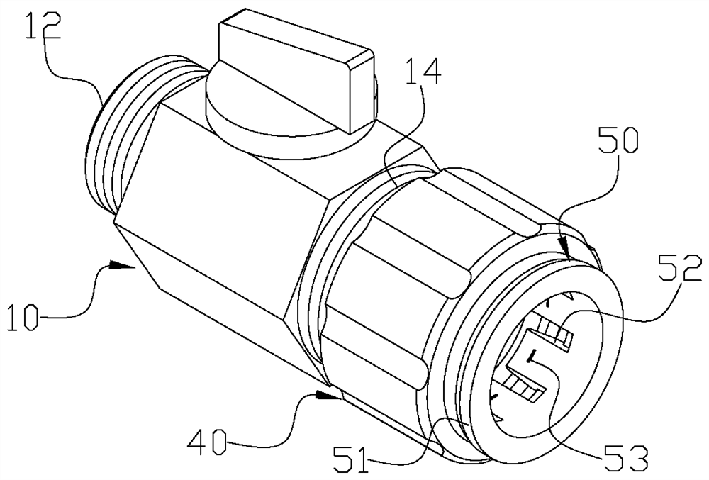
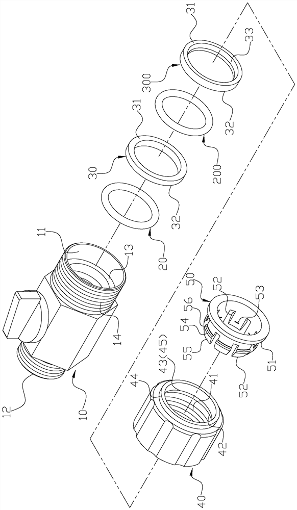
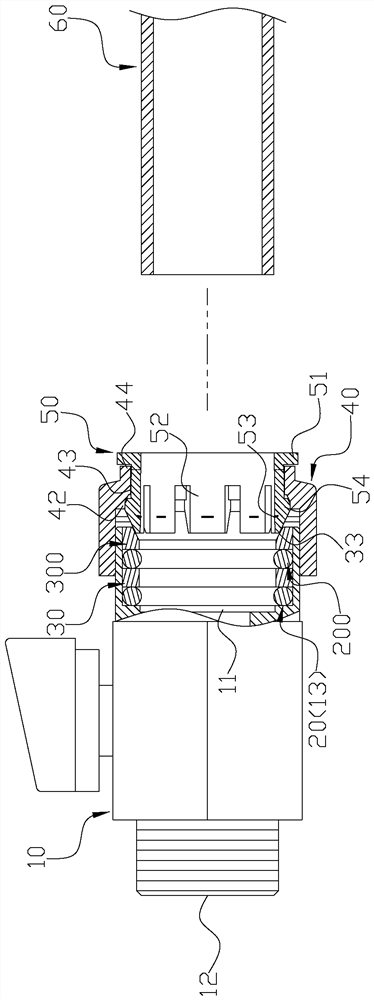
[0036] First, as Figure 1 to Figure 4 As shown, it includes: a joint body 10, a first O-ring seal 20, a second O-ring seal 200, a first auxiliary positioning ring 30, a second auxiliary positioning ring 300, and a locking screw 40 and a connecting seat 50, wherein the connector body 10 has a first opening 11 and a second opening 12 which are connected and conducted. The first opening 11 is provided with a ring protrusion 13. The outer edge of the opening 11 is provided with a first thread segment 14 , the first auxiliary positioning ring 30 and the second auxiliary positioning ring 300 each have a first end 31 , a second end 32 , an inner ring portion and an outer ring portion , the middl...


PUM


Abstract

The invention relates to a pipe joint structure which comprises a joint body, a first O-shaped seal, a second O-shaped seal, a first auxiliary positioning ring, a second auxiliary positioning ring, alocking screw and a connecting seat; the joint body is provided with a first opening, a second opening and a ring protrusion, and the joint body is provided with a first thread segment with respect tothe outer edge of the first opening; an action inclined surface is formed on the second auxiliary positioning ring, and the inner edge of the locking screw is provided with a second thread segment, afirst step-shaped part and a second step-shaped part. A reduced diameter section is connected to one end of the locking screw by the formation of the second step-shaped part, and an inclined surfaceis formed at the corner of the second step-shaped part adjacent to the first step-shaped part, and a plurality of elastic pieces are arranged on the connecting seat, and the elastic pieces are provided with metal claws, barbs, inclined parts and inclined surfaces.

Description

technical field [0001] The present invention relates to a pipe joint structure, in particular to a pipe joint structure with good positioning force. Background technique [0002] Currently known pipe joint structures, such as Figure 10 As shown, the pipe joint 80 mainly includes: a joint body 81, an O-shaped seal 82, a snap ring 83 and a connecting seat 84, wherein the joint body 81 has a first opening 811 connected to the A second opening 812, the first opening 811 is provided with an annular protrusion 813 and an annular groove 814, the retaining ring 83 has an annular elastic flange 831 and a plurality of retaining teeth 832 disposed on the flange 831, the connecting seat One end of 84 is provided with an enlarged lug 841, and the lug 841 is used to press the connecting seat 84 inwardly, and the other end is extended with a plurality of elastic pieces 842 in a mutually spaced manner, and the outer side of each elastic piece 842 is A barb 843 is formed; when in use, the ...

Claims


Application Information

Patent Timeline
Patent Type & Authority Patents(China)
IPC IPC(8): F16L19/03F16L19/065
CPCF16L19/0206F16L19/0218F16L19/065
Inventor 赖鸿麟
Owner WEN SHENG FU CO LTD
Why Eureka
Try Eureka