Farmland anti-sinking tractor

A locomotive and field technology, applied in the field of anti-subsidence locomotives in the field, can solve problems such as no mechanical self-rescue device, the machine cannot continue to work, and the machine is stuck in the quagmire.

Inactive Publication Date: 2017-04-26
谢航洋
View PDF6 Cites 0 Cited by
  • Summary
  • Abstract
  • Description
  • Claims
  • Application Information

AI Technical Summary

Problems solved by technology

[0002] At present, when agricultural machinery such as paddy field plowing, sowing, cutting seedlings, and harvesting encounter deep-footed mud fields and local small puddles in paddy fields, they usually get stuck in the quagmire due to carelessness or ignorance. People help push and pull or use other vehicles to get out of the predicament. Although agricultural machinery manufacturers have made many improvements to solve the problem, such problems still exist. This not only consumes a lot of manpower and material resources, but also delays farming. It is easy to cause safety accidents
[0003] For example, the cultivator mentioned in the invention whose patent number is CN201410556759.8 includes: diesel engine, diesel engine base, base assembly, driving wheel, traction frame, double-tube plow assembly, steering handle, handrail, throttle control handle , clutch mechanical joystick, gear lever, clutch cable, transmission gearbox, throttle cable, V-belt pulley, pulley guard, V-belt, etc.; but there is no self-rescue device when the machine falls into the quagmire. Unable to continue working, it is very troublesome and inconvenient to use other forces to drag the machine out. However, it is very common for the machine to get stuck in the mud in the field

Method used


Image

  • Farmland anti-sinking tractor
  • Farmland anti-sinking tractor

Examples


Embodiment 1

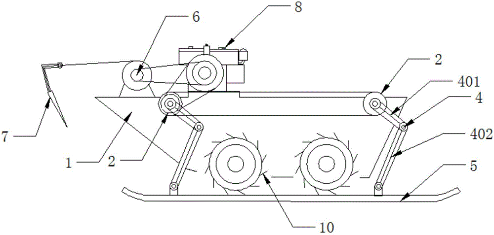
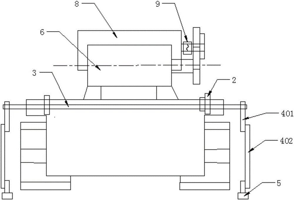
[0024] Such as figure 1 and figure 2 As shown, a field anti-subsidence locomotive comprises a main body 1 and an engine 8 providing power for the locomotive. The front and rear ends of the main body 1 are respectively equipped with linkage axles 3, and the linkage axles 3 are provided with pulleys. The belt pulley of the power output shaft of the belt pulley and the engine 8 is connected by a belt. The two ends of the linkage wheel shaft 3 are provided with a linkage sprocket 2. The ends are equipped with a self-rescue lifting rocker 4, and the self-rescue lifting rocker 4 includes a rocker 401 and a connecting rod 402. One end of the rocking arm 401 is connected to the linkage wheel shaft 3, and the other end is connected to the connecting rod 402. The connecting rod The other end of 402 links to each other with slide plate 5; Described main vehicle body 1 front end is provided with wire rope sheave 6, connects L type traction hook 7 on the wire rope, and described wire rop...

Embodiment 2

[0027] Such as figure 1 and figure 2 As shown, a field anti-subsidence locomotive comprises a main body 1 and an engine 8 providing power for the locomotive. The front and rear ends of the main body 1 are respectively equipped with linkage axles 3, and the linkage axles 3 are provided with pulleys. The belt pulley of the power output shaft of the belt pulley and the engine 8 is connected by a belt. The two ends of the linkage wheel shaft 3 are provided with a linkage sprocket 2. The ends are equipped with a self-rescue lifting rocker 4, and the self-rescue lifting rocker 4 includes a rocker 401 and a connecting rod 402. One end of the rocking arm 401 is connected to the linkage wheel shaft 3, and the other end is connected to the connecting rod 402. The connecting rod The other end of 402 links to each other with slide plate 5; Described main vehicle body 1 front end is provided with wire rope sheave 6, connects L type traction hook 7 on the wire rope, and described wire rop...

Embodiment 3

[0030] Such as figure 1 and figure 2 As shown, a field anti-subsidence locomotive comprises a main body 1 and an engine 8 providing power for the locomotive. The front and rear ends of the main body 1 are respectively equipped with linkage axles 3, and the linkage axles 3 are provided with pulleys. The belt pulley of the power output shaft of the belt pulley and the engine 8 is connected by a belt. The two ends of the linkage wheel shaft 3 are provided with a linkage sprocket 2. The ends are equipped with a self-rescue lifting rocker 4, and the self-rescue lifting rocker 4 includes a rocker 401 and a connecting rod 402. One end of the rocking arm 401 is connected to the linkage wheel shaft 3, and the other end is connected to the connecting rod 402. The connecting rod The other end of 402 links to each other with slide plate 5; Described main vehicle body 1 front end is provided with wire rope sheave 6, connects L type traction hook 7 on the wire rope, and described wire rop...


PUM

PropertyMeasurementUnit
Lengthaaaaaaaaaa
Corneraaaaaaaaaa
Lengthaaaaaaaaaa

Abstract

The invention provides a farmland anti-sinking tractor which comprises a main tractor body and an engine that supplies power to the tractor. The front end and the back end of the main tractor body are respectively provided with a linkage wheel shaft. Each linkage wheel shaft is provided with a belt pulley. The belt pulley is connected with the belt pulley of an engine power output shaft through a belt. Two ends of the linkage wheel shaft are provided with linkage sprocket wheels. The linkage sprocket wheels at the same side of the front linkage wheel shaft and the back linkage wheel shaft are connected by means of a chain. Two ends of the linkage wheel shaft are respectively provided with a self-rescuing liftable rocker arm. The self-rescuing liftable rocker arm comprises a rocker arm and a connecting rod. One end of the rocker arm is connected with the linkage wheel shaft, and the other end is connected with the connecting rod. The other end of the connecting rod is connected with a sliding table. The front end of the main tractor body is provided with a wire rope reel. The wire rope is connected with an L-shaped traction hook. The wire rope reel is connected with the belt pulley of the engine power output shaft through the belt.

Description

technical field [0001] The invention relates to an agricultural machine, in particular to a field anti-subsidence locomotive. Background technique [0002] At present, when agricultural machinery such as paddy field plowing, sowing, cutting seedlings, and harvesting encounter deep-footed mud fields and local small puddles in paddy fields, they usually get stuck in the quagmire due to carelessness or ignorance. People help push and pull or use other vehicles to get out of the predicament. Although agricultural machinery manufacturers have made many improvements to solve the problem, such problems still exist. This not only consumes a lot of manpower and material resources, but also delays farming. It is easy to cause safety accidents. [0003] For example, the cultivator mentioned in the invention whose patent number is CN201410556759.8 includes: diesel engine, diesel engine base, base assembly, driving wheel, traction frame, double-tube plow assembly, steering handle, handr...

Claims


Application Information

Patent Timeline
IPC IPC(8): A01B51/02
CPCA01B51/02
Inventor 谢航洋
Owner 谢航洋
Why Eureka
Try Eureka