Bag removal mechanism, device and method

A technology of motion mechanism and mounting parts, which is applied in the direction of conveyor, unstacking, transportation and packaging of objects, and can solve problems such as high labor intensity, poor versatility, and harsh working environment

Pending Publication Date: 2020-09-25
CHINA HEFEI TAIHE OPTOELECTRONICS TECH
View PDF0 Cites 0 Cited by
  • Summary
  • Abstract
  • Description
  • Claims
  • Application Information

AI Technical Summary

Problems solved by technology

Manual unstacking is labor-intensive and the working environment is harsh
[0003] For a stack composed of bagged goods with good fluidity, large deformation or large ups and downs, the upper layer of bagged goods is easily stuck in the gap between the lower layer of bagged goods, and the existing feed bag destacking mechanism is When unpacking the bag, it is not easy to unpack the bag stably, and the versatility is poor

Method used


Image

  • Bag removal mechanism, device and method
  • Bag removal mechanism, device and method
  • Bag removal mechanism, device and method

Examples


no. 1 example

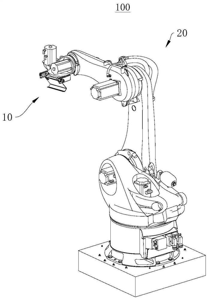
[0040] see figure 1 , figure 1 It is a structural schematic diagram of the bag unpacking mechanism 10 applied to the bag unpacking device 100 provided by the first embodiment of the present invention.

[0041] The first embodiment of the present invention provides a bag unpacking mechanism 10. The bag unpacking mechanism 10 is used for unpacking a stack of goods 900, especially a stack of goods 900 containing bagged goods 910. The bag unpacking mechanism 10 has relatively stable bag unpacking, And the characteristics of better versatility. The bag unpacking mechanism 10 can be applied to scenarios such as bag unpacking device 100 , unstacking system, automated warehouse, logistics system, or automated factory.

[0042] Taking the bag unpacking mechanism 10 applied to the bag unpacking device 100 as an example, the bag unpacking device 100 can include a bag unpacking mechanism 10 and a bag unpacking motion mechanism 20, the bag unpacking mechanism 10 is connected to the bag u...

no. 2 example

[0076] see Figure 7 , Figure 7 It is a schematic flowchart of the bag unpacking method provided by the second embodiment of the present invention.

[0077] The second embodiment of the present invention provides a bag unpacking method, which also has the characteristics of relatively stable bag unpacking and good versatility. This bag unpacking method can be applied to the above-mentioned bag unpacking device 100 . It should be noted that the basic principles and technical effects of the bag-unpacking method provided in this embodiment are the same as those of the above-mentioned embodiment. Corresponding content.

[0078] When the bag opening device 100 does not include the second bag opening member 13, the bag opening method may include:

[0079] Step S101: The bag unpacking movement mechanism 20 drives the mounting part 15 to move, so that the first hooking section 111 rests on the top of the cargo stack 900 and slides along the top of the cargo stack 900, and makes t...


PUM


Abstract

The invention discloses a bag removal mechanism, device and method, and relates to the technical field of logistics equipment. The bag removal mechanism comprises an installing piece and a first bag removal piece. The first bag removal piece comprises a first hooking section and a second hooking section in sequential connection. The first hooking section and the second hooking section jointly define a hooking groove and are used for hooking bagged goods. An installing piece is used for being connected with a bag removal moving mechanism of the bag removal device so as to be driven by the bag removal moving mechanism to move. The end, away from the first hooking section, of the second hooking section is rotationally connected to the installing piece, and the second hooking section can rotate relative to the installing piece, so that the first hooking section can rotate into a gap between the bagged goods under the action of gravity when sliding along the top of a goods stack along withthe installing piece, and the hooking groove can correspond to the edge of the bagged goods. The bag removal mechanism, device and method have the advantages of being stable in bag removal and high inuniversality.

Description

technical field [0001] The invention relates to the technical field of logistics equipment, in particular to a bag unpacking mechanism, device and method. Background technique [0002] In grain, feed, chemical and other industries, goods are mainly packaged in bags and stacked on pallets for easy handling and storage. When carrying out operations such as foreign transport, loading, and material loading of bagged goods, it is often necessary to manually unpack the bagged goods from the stack. The manual unstacking operation is labor-intensive and the working environment is harsh. [0003] For a stack composed of bagged goods with good fluidity, large deformation or large ups and downs, the upper layer of bagged goods is easily stuck in the gap between the lower layer of bagged goods, and the existing feed bag destacking mechanism is When carrying out bag unpacking operation, it is difficult to unpack stably, and the versatility is relatively poor. [0004] In view of this,...

Claims


Application Information

Patent Timeline
Patent Type & Authority Applications(China)
IPC IPC(8): B65G61/00
CPCB65G61/00B65G2201/0238
Inventor 许大红石江涛张杰黄盼龙
Owner CHINA HEFEI TAIHE OPTOELECTRONICS TECH
Why Eureka
Try Eureka