Underwater installation recoverer and recovery method thereof

A technology of underwater equipment and recovery device, applied in the direction of underwater operation equipment, ships, ship salvage, etc., can solve the problems of increasing the cost of re-deployment, the release mechanism is not completely reliable, and the equipment monitoring data is lost, etc., and achieve stable recovery. Equipment, simple structure, the effect of reducing resistance

Inactive Publication Date: 2013-05-08
ZHANGZIDAO GRP
View PDF0 Cites 0 Cited by
  • Summary
  • Abstract
  • Description
  • Claims
  • Application Information

AI Technical Summary

Problems solved by technology

[0003] For equipment deployed underwater, commands can be issued through the control component to make the releaser release the floating body and the objects to be recovered connected to it, and can be dragged or lifted through the docking device; however, this method first keeps the counterweight in the Seabed, which not only increases the cost of re-deployment, but also has ecological hazards because new counterweights are required each time; secondly, the release mechanism is not completely reliable, which will transfer the usually expensive equipment and data in the equipment. Stranded on the seabed, resulting in complete loss of expensive equipment and its monitoring data
Or use unmanned remote-controlled submersibles to salvage stranded equipment, but the special equipment required for this method is complicated and expensive
In shallow water, divers can be used to find and salvage, but this method is expensive, time-consuming, and extremely unsafe, especially in poor sea conditions

Method used


Image

  • Underwater installation recoverer and recovery method thereof
  • Underwater installation recoverer and recovery method thereof
  • Underwater installation recoverer and recovery method thereof

Examples


Embodiment Construction

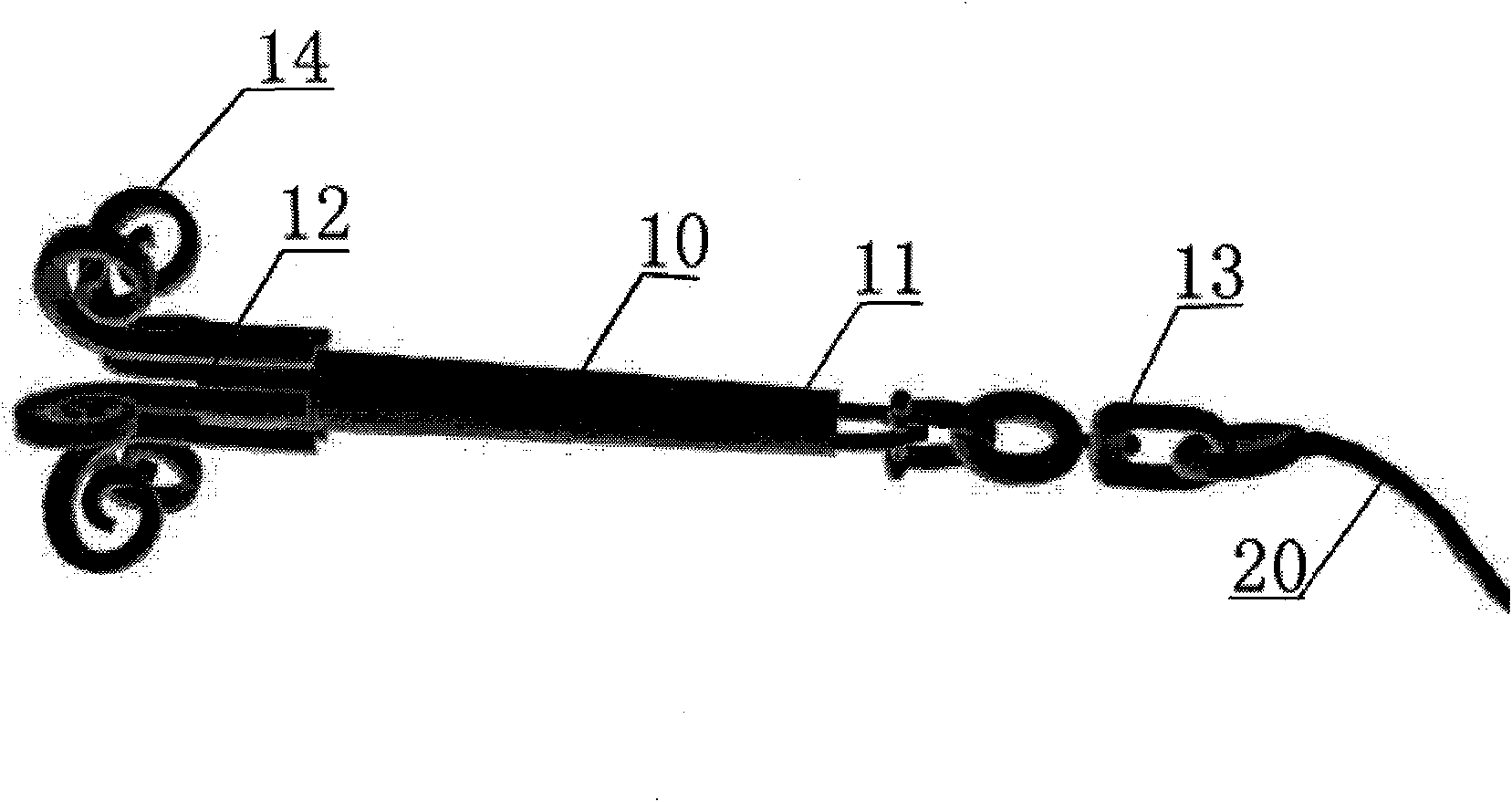
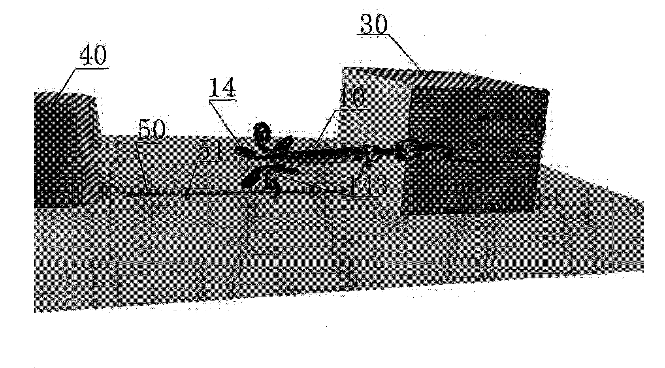
[0036] The structure of the underwater equipment recovery device of the present invention is simple, approximately rod-shaped, with a recovery cable at one end and several hooks at the other end. By pulling the recovery cable, the hooks can hook the hooking part of the recovered object, so that the underwater The equipment and its counterweight are recovered at the same time. The recovery method is safe and reliable, and the operation is convenient, time-saving and labor-saving.

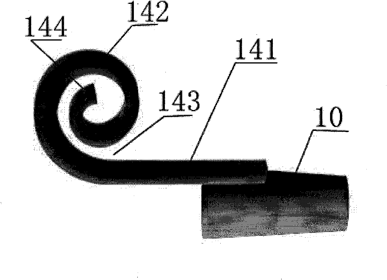
[0037] figure 1 It is a structural schematic diagram of the underwater equipment recoverer of the present invention, such as figure 1 As shown, one end of the rod body 10 is connected to the recovery cable 20, and the other end is provided with six claws 14. The rod body 10 is in the shape of a cone. The rod body 10 is welded with six hooks 14 at the bottom 12 with a larger section. The end 11 of the rod body 10 with a smaller cross-section is provided with a swivel assembly 13 , which can rotate f...


PUM


Abstract

The invention relates to an underwater installation recoverer. In the recoverer , a recovery rope is positioned at one end of a rod body; more than three claws are uniformly distributed on the outside surface of the other end of the rod body; the claws bend from a straight rod part to form a bent part; the straight rod part is connected with the outside surface of the rod body; the bent part has a spiral shape with more than one circle of spiral curve; a hook mouth is formed between a closing point capable of forming a closed curve of the bent part and the straight rod part; the gap at the position of the hook mouth is more than or equal to the size of the hook part of an object to be recovered; and when at least one claw is on the same bottom plane with the object to be recovered, the vertical height of the hook mouth is more than or equal to the vertical height of the hooked part of the object to be recovered. The invention also relates to a method for recovering the underwater installation recoverer. When the recoverer is on the same bottom plane with the object to be recovered, at least two claws contact with the bottom plane to allow the hooked part to enter the recoverer along the gap of the bent part from the hook mouth to capture the recoverer; and the object to be recovered is taken way, so the recoverer can recover connected equipment. The underwater installation recoverer has a simple structure; the recovery method has a high recovery rate and simple, quick, labor-saving and safe operation.

Description

technical field [0001] The invention relates to recovery of underwater equipment, in particular to a recoverer for recovering underwater equipment and a recovery method thereof. Background technique [0002] With the continuous development and utilization of the ocean, it is usually necessary to recover, salvage, or clean these objects when operating at sea or deploying marine monitoring equipment underwater. [0003] For equipment deployed underwater, commands can be issued through the control component to make the releaser release the floating body and the objects to be recovered connected to it, and can be dragged or lifted through the docking device; however, this method first keeps the counterweight in the Seabed, which not only increases the cost of re-deployment, but also has ecological hazards because new counterweights are required each time; secondly, the release mechanism is not completely reliable, which will transfer the usually expensive equipment and data in t...

Claims


Application Information

Patent Timeline
Patent Type & Authority Patents(China)
IPC IPC(8): B63C7/02B63C11/50
Inventor 臧有才张晓芳杨殿群张永国
Owner ZHANGZIDAO GRP
Why Eureka
Try Eureka