Automatic vending machine with anti-rainwater device

A vending machine, rain-proof technology, applied in the direction of handling coins or valuable banknotes, coin-free or similar appliances, coin-operated equipment for distributing discrete items, etc. To solve problems such as sex, the structure is reasonable and simple, the production cost is low, and the installation is convenient.

Inactive Publication Date: 2019-02-26
YANTAI ZHIXING INTPROP CONSULTATION SERVICES CO LTD
9 Cites 0 Cited by

AI-Extracted Technical Summary

Problems solved by technology

[0003] In the prior art, most of the common beverage vending machines are deployed outdoors. However, the cur...

Abstract

The invention discloses an automatic vending machine with anti-rainwater device. The machine comprises a base, a horizontal plate, a vertical rod, a short rod, a rainwater shielding plate, an upper air pressure rod, a lower air pressure rod, a collection port, a water falling pipe, buckles, a motor base, a mounting base, a rotation shaft and the like. The automatic vending machine is reasonable and simple in structure, low in production cost and convenient to mount, and the rainwater shielding plate can be controlled to be opened or closed for rainwater prevention through the upper air pressure rod and the lower air pressure rod; a motor drives a second bevel gear to rotate, the second bevel gear drives a first bevel gear, the rotation shaft rotates accordingly, and waterproof cloth at thetop of the rotation shaft covers the upper portion of the vending machine for rainwater prevention; the collection port is formed for collecting rainwater, and the rainwater is discharged through thewater falling pipe, so that rainwater prevention is conduced; by arranging a slidable rainwater shielding cover, when rainwater exists, the rainwater shielding cover slides to the upper portion of the vending machine for rainwater shielding, and when no rainwater exists, the rainwater shielding cover is removed.

Application Domain

Coin-freed apparatus detailsApparatus for dispensing discrete articles

Technology Topic

Rainwater harvestingEngineering +2

Image

  • Automatic vending machine with anti-rainwater device
  • Automatic vending machine with anti-rainwater device
  • Automatic vending machine with anti-rainwater device

Examples

  • Experimental program(1)

Example Embodiment

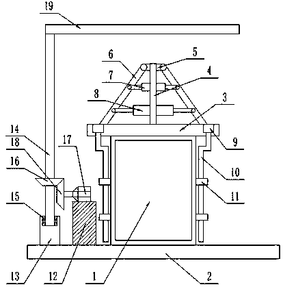
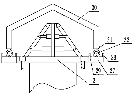
[0023] Such as Figure 1 to Figure 3 As shown, this specific embodiment adopts the following technical solutions: A vending machine with a rain-proof device, including: a vending machine 1, further including a base 2, a horizontal plate 3, a vertical pole 4, a short pole 5, and a rain shield 6. , Upper air pressure rod 7, lower air pressure rod 8, collection port 9, downpipe 10, buckle 11, motor seat 12, mounting seat 13, rotating shaft 14, bearing 15, first umbrella tooth 16, motor 17, and second umbrella tooth 18 And tarpaulin 19; a vending machine 1 is fixedly connected to the center of the upper surface of the base 2; a motor base 12 and a mounting base 13 are fixedly connected to the left side of the upper surface of the base 2; the top of the vending machine 1 A horizontal plate 3 is fixedly connected to the upper surface; both sides of the upper surface of the horizontal plate 3 are provided with a collection port 9; each collection port 9 is provided with a downpipe 10; the downpipe 10 is fixedly connected to the On both sides of the vending machine 1, a vertical pole 4 is fixedly connected to the center of the upper surface of the horizontal plate 3; both sides of the top end of the vertical pole 4 are fixedly connected to a short pole 5; the short pole 5 A rain shield 6 is hinged on both ends of the vertical rod 4; an upper air pressure rod 7 is fixedly connected to both sides of the middle end of the vertical rod 4; a lower air pressure rod 7 is fixedly connected to both sides of the lower end of the vertical rod 4 Air pressure rod 8; the output ends of the upper air pressure rod 7 and the lower air pressure rod 8 are hinged on the rain shield 6; the end of the rotating shaft 14 is movably connected to the mounting seat 13 through the bearing 15; the outer surface of the rotating shaft 14 A first bevel tooth 16 is fixedly connected to the upper part; a motor 17 is fixedly connected to the motor base 12; a second bevel tooth 18 is fixedly connected to the output shaft of the motor 17 and the second bevel tooth 18 is The first umbrella teeth 16 mesh with each other; a waterproof cloth 19 is fixedly connected to the top of the rotating shaft 14.
[0024] The specific structure of the waterproof cloth 19 is as follows: includes a substrate 20, a metal mesh 21, a wear-resistant layer 22, a civil cloth buffer layer 23, an adhesive layer 24, an isolation film 25 and a fireproof layer 26; on the lower surface of the substrate 20 A metal mesh 21 is fixedly connected; a wear-resistant layer 22 is fixedly connected to the lower surface of the metal mesh 21; a civil cloth buffer layer 23 is fixedly connected to the lower surface of the wear-resistant layer 22; the civil cloth An adhesive layer 24 is fixedly connected to the lower surface of the buffer layer 23; an isolating film 25 is fixedly connected to the lower surface of the adhesive layer 24; a fireproof layer 26 is fixedly connected to the lower surface of the isolating film 25 .
[0025] It also includes a platform 27, a first limit plate 28, a second limit plate 29, a rain cover 30, a connecting rod 31 and a pulley 32; a platform 27 is fixedly connected to both ends of the horizontal plate 3; A first limit plate 28 is fixedly connected to the left side of the upper surface of the platform 27; a second limit plate 29 is fixedly connected to the right side of the upper surface of the platform 27; the rain cover 30 is located on the horizontal plate 3 Directly above; the lower ends of both sides of the horizontal plate 3 are fixedly connected with a connecting rod 31; the ends of the connecting rod 31 are connected with a pulley 32; the pulley 32 is located on the corresponding platform 27.
[0026] Wherein, the pulley 32 is provided with anti-skid devices; the motor 17 is a variable frequency motor or a servo motor; the bearing 15 is a ball bearing; the motor seat 12 is a rubber motor seat; the buckle 11 is U-shaped shape.
[0027] The use state of the present invention is: the present invention has a reasonable and simple structure, low production cost, and convenient installation. The rain shield 6 can control the opening and closing of the rain shield 6 according to the upper air pressure rod 7 and the lower air pressure rod 8 to prevent rain; The motor 17 of the present invention drives the second umbrella tooth 18 to rotate, and the second umbrella tooth 18 drives the first umbrella tooth 16 to rotate, so that the rotating shaft 14 rotates. The waterproof cloth 19 on the top of the rotating shaft 14 covers the top of the vending machine 1 to prevent rain; The invention sets a collection port 9 to collect rainwater, and drains rainwater through a downpipe 10 to prevent rainwater; the present invention sets a slidable rain cover 30, when it encounters rainwater, it slides to the top of the vending machine 1 to avoid rain. When it rains, just remove the rain cover 30.
[0028] The above shows and describes the basic principles and main features of the present invention and the advantages of the present invention. Those skilled in the art should understand that the present invention is not limited by the above-mentioned embodiments. The above-mentioned embodiments and the description in the specification are only illustrative of the present invention. In principle, without departing from the spirit and scope of the present invention, the present invention will have various changes and improvements. These changes and improvements fall within the scope of the claimed invention. The scope of the claimed invention is determined by the appended rights. Definition of requirements and their equivalents.

PUM

no PUM

Description & Claims & Application Information

We can also present the details of the Description, Claims and Application information to help users get a comprehensive understanding of the technical details of the patent, such as background art, summary of invention, brief description of drawings, description of embodiments, and other original content. On the other hand, users can also determine the specific scope of protection of the technology through the list of claims; as well as understand the changes in the life cycle of the technology with the presentation of the patent timeline. Login to view more.

Similar technology patents

Multifunctional urban road cleaning vehicle

InactiveCN102425129ASimple and reasonable structureSimple and flexible operation
Owner:刘和平

Metal powder pre-pressing device and method for polycrystalline diamond wire-drawing die bushing

ActiveCN104708002AStrong adaptability of processing technologySimple and reasonable structure
Owner:北京迪蒙吉意超硬材料技术有限公司

Classification and recommendation of technical efficacy words

  • Simple and reasonable structure
  • reduce manufacturing cost
Why Eureka
Try Eureka