
A multifunctional shooting machine

A shooting machine and multi-functional technology, applied in gymnastics equipment, coordination training equipment, sports accessories, etc., can solve the problems that players cannot be trained to shoot and lower body strength cannot be exercised, and achieve the effect of increasing interest

Active Publication Date: 2020-05-19
QUFU NORMAL UNIV +1
View PDF10 Cites 0 Cited by
  • Summary
  • Abstract
  • Description
  • Claims
  • Application Information

AI Technical Summary

Problems solved by technology

The existing shooting machine has the following disadvantages: (1) the shooting machine mainly exercises the player's upper body strength, but the player's lower body strength cannot be exercised; (2) drift shooting is an important skill in basketball, and the player jumps sideways and Throwing the basketball can effectively prevent being blocked by the opponent's player, which requires the player to have good balance and anticipation ability. Although the existing shooting machine drives the basket to move through the driving mechanism, it can train the player's anticipation ability, but it cannot be trained. The player's shooting ability to overcome inertia

Method used


Image

  • A multifunctional shooting machine
  • A multifunctional shooting machine
  • A multifunctional shooting machine

Examples


Embodiment 1

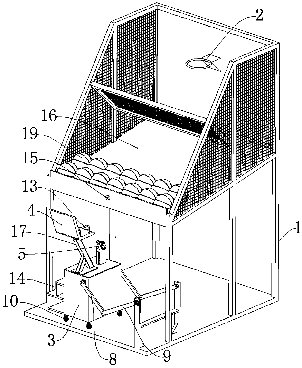
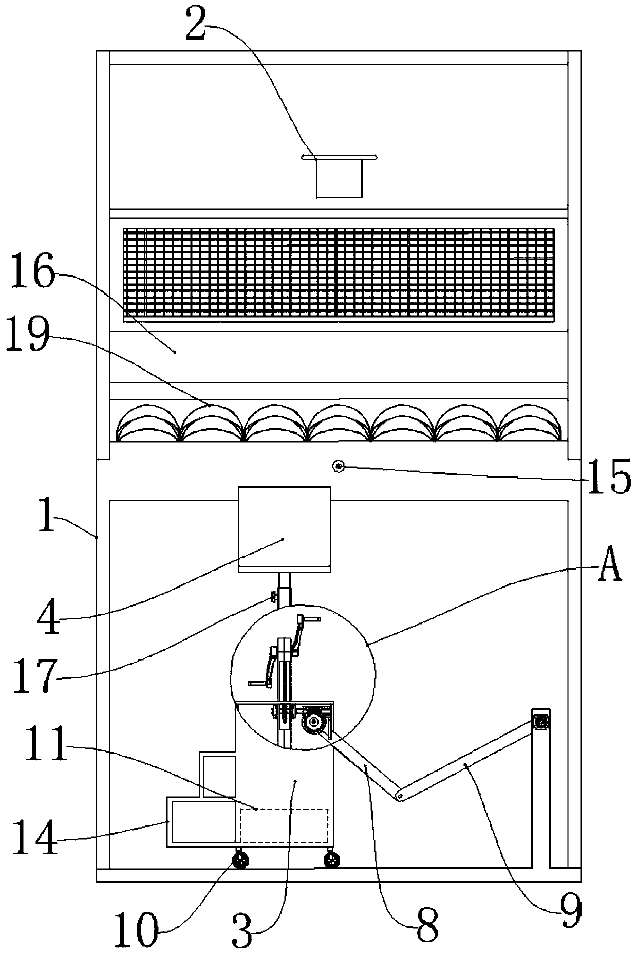
[0023] Figure 1 to Figure 4 Embodiment 1 of the present invention is shown. As shown in the figure, a multifunctional shooting machine includes a frame 1, a basket 2, a left and right moving mechanism and an anti-overturning mechanism.

[0024] The basket 2 is fixed on the frame 1.

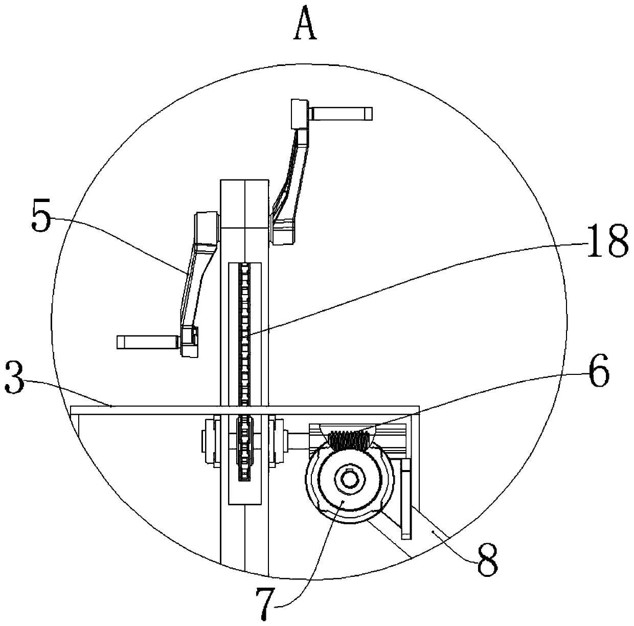
[0025] The left and right moving mechanism comprises a mobile trolley 3, a seat 4, a first crank 5, a worm screw 6, a worm wheel 7, a second crank 8 and a connecting rod 9.

[0026] The bottom of the mobile dolly 3 is provided with wheels 10 . The dolly 3 is provided with a ladder 14 so that the player boards the dolly 3 .

[0027] Seat 4 is installed on mobile dolly 3 by elevating support 17, is convenient to adjust the height of seat 4 according to the stature of player. In order to prevent the player from being thrown out of the seat 4 under the effect of inertia, the both sides of the seat 4 are fixedly provided with protective fences 13 .

[0028] Such as figure 2 with image 3 As sho...

Embodiment 2

[0033] Such as Figure 5 As shown, the second embodiment is different from the first embodiment in that the anti-overturning mechanism is an anti-overturning guide column 12, and the anti-overturning guide column 12 is fixedly arranged on the frame 1 and its axis is in the left-right direction, and the mobile trolley 3 and the anti-overturning guide column The guide column 12 is slidably connected.


PUM


Abstract

The invention relates to the technical field of sports equipment, in particular to a multifunctional basketball shooting machine. The multifunctional basketball shooting machine comprises a machine frame, a basket and a left-right moving mechanism, wherein the basket is fixedly arranged on the machine frame; the left-right moving mechanism comprises a moving trolley, a seat, a first crank, a worm,a worm wheel, a second crank and a connecting rod. The first crank is installed on the moving trolley, and the rotation axis of the first crank is in the left-right direction. The worm and the worm wheel are both installed on the moving trolley, the axis of the worm is in the left-right direction, the axis of the worm wheel is in the front-back direction, the worm meshes with the worm wheel, andthe worm is connected with the first crank through a transmission mechanism. One end of the second crank is fixedly connected with the worm wheel, the other end of the second crank is in pivot joint with the connecting rod, and the connecting rod is in pivot joint with the machine frame. According to the multifunctional basketball shooting machine, a player pedals the first crank as power to drivethe moving trolley, so that the player moves left and right relative to the basket when shooting, interest is increased, and the lower limb strength, the anticipation ability, the balance ability andthe drifting basketball shooting ability of the player are trained.

Description

technical field [0001] The invention relates to the technical field of sports equipment, in particular to a multifunctional basketball shooting machine. Background technique [0002] Shooting machine, also known as basketball machine and street basketball machine, is a kind of sports and leisure equipment that separates the shooting action in basketball, and scores points according to the number of shots made by players within a certain period of time. In the early days of the shooting machine, the basket was fixed on the backboard. Later, in order to increase the fun and train the player's ability to predict, a shooting machine with a movable basket appeared. For details, please refer to the application number 200520129597.6 and application number It is 201220466191.7, application number is 201020545455.9 and other Chinese patents. The existing shooting machine has the following disadvantages: (1) the shooting machine mainly exercises the player's upper body strength, but ...

Claims


Application Information

Patent Timeline
Patent Type & Authority Patents(China)
IPC IPC(8): A63B63/08A63B69/00A63B22/08A63B71/06
CPCA63B22/0605A63B63/083A63B69/0071A63B71/0619A63B2220/805
Inventor 刘芳
Owner QUFU NORMAL UNIV
Learn More