Groove blade coating clamp

A blade and coating technology, applied in the field of grooved blade coating fixture, can solve the problems of unstable position, easy to drop the grooved blade, inconvenient operation, etc., and achieve the effect of convenient operation, convenient insertion and fixation, and good consistency

Inactive Publication Date: 2019-03-01
ZHUZHOU CHAOYU INDAL
View PDF5 Cites 1 Cited by
  • Summary
  • Abstract
  • Description
  • Claims
  • Application Information

AI Technical Summary

Problems solved by technology

[0002] At present, the coating spring bar is mainly used to fix the slot blade. The slot blade coating spring bar is stuck on the side of the slot blade by a spring, and the position is not fixed. It needs to be manually corrected in the process of inserting the slot blade. , the operation is inconvenient, and the efficiency is low, and it is easy to drop the blade

Method used


Image

  • Groove blade coating clamp
  • Groove blade coating clamp

Examples


Embodiment Construction

[0019] In order to make the content of the present invention more clearly understood, the present invention will be further described in detail below based on specific embodiments and in conjunction with the accompanying drawings.

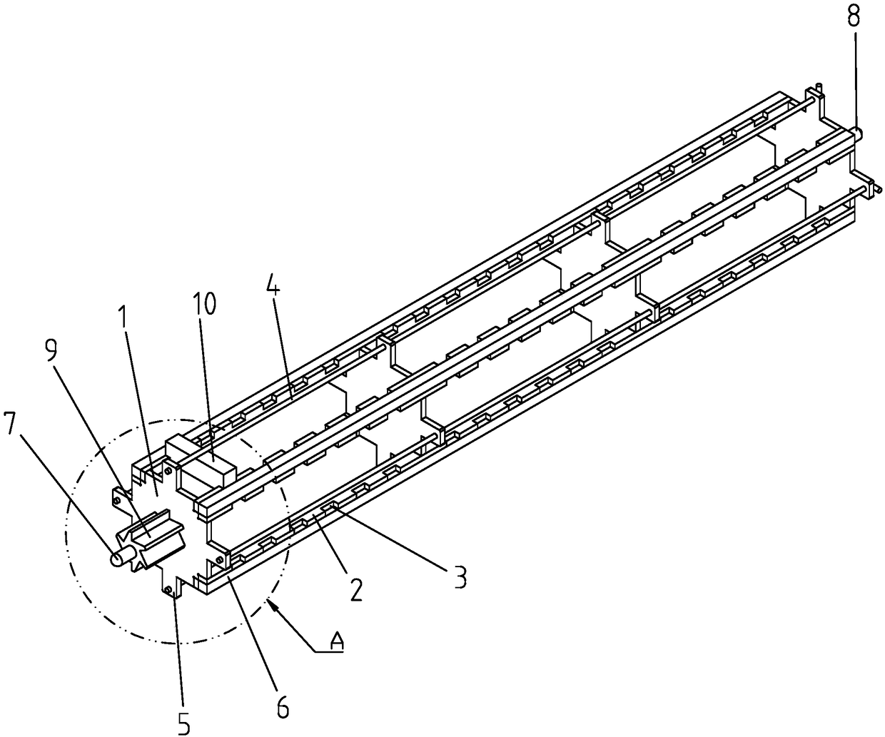
[0020] Such as figure 1 Shown, a grooved blade coating fixture, it includes:

[0021] At least two supporting plates 1 arranged side by side;

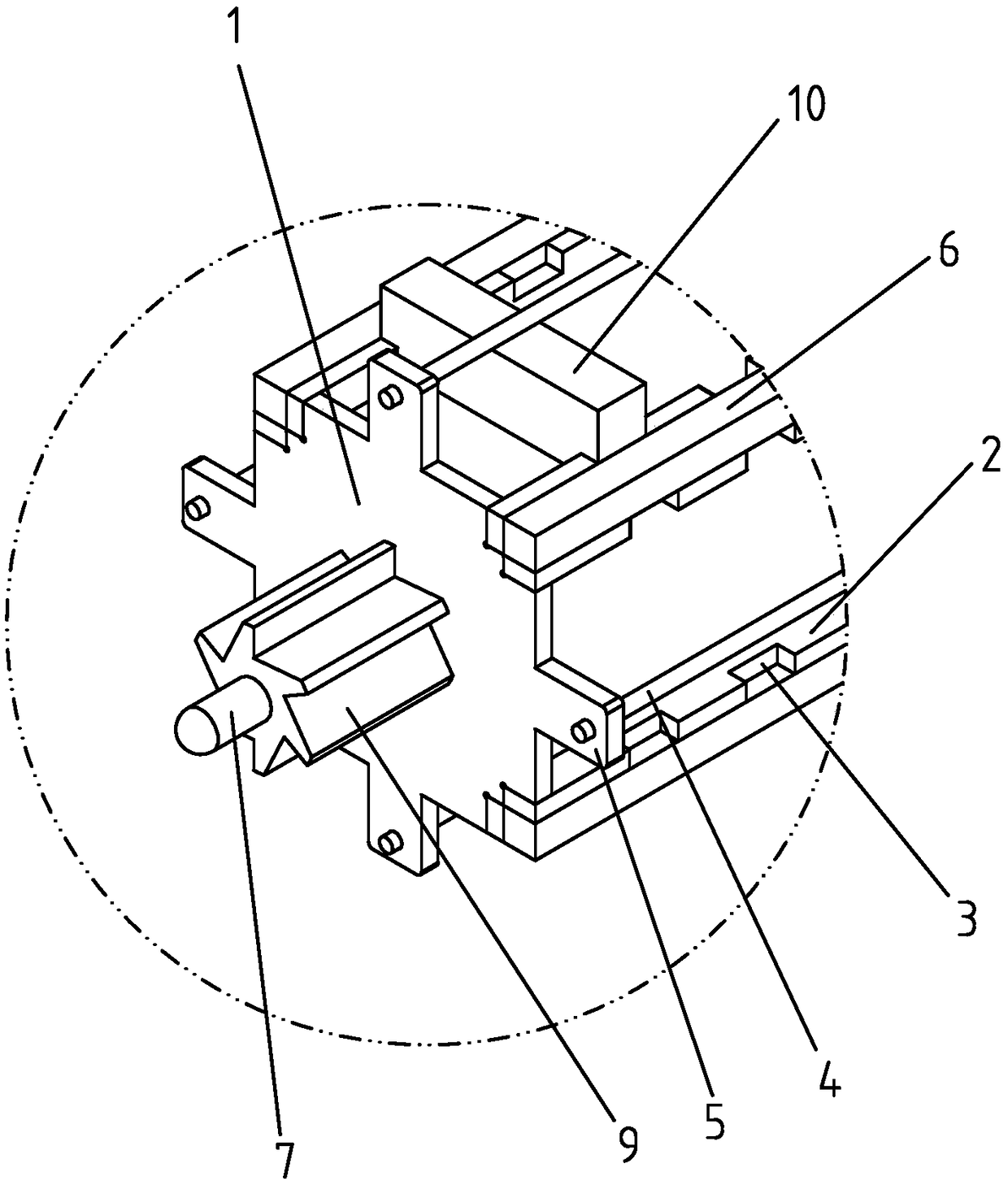
[0022] At least one clamping strip group, the clamping strip group includes two clamping strips 2, the clamping strips 2 are connected to all support plates 1, so that the clamping strips 2 are supported by the support plates 1, and the clamping strips A plurality of notches 3 are arranged side by side on the 2, and the notches 3 on the two clamping blades 2 of the clamping blade group correspond one by one, and the groove blades 10 are inserted into the two corresponding notches 3;

[0023] One-to-one corresponding blade retaining strips 4 of the clamping strip group, the blade retaining strips 4 are det...


PUM


Abstract

The invention discloses a groove blade coating clamp. The groove blade coating clamp comprises at least two supporting plates which are arranged side by side, at least one blade blocking strip group and blade baffle strips which are in one-to-one correspondence to the blade blocking strip group, wherein the blade blocking strip group comprises two blade blocking strips which are connected with allsupporting plates, so that the blade blocking strips are supported by the supporting plates; a plurality of slot holes are formed in the blade blocking strips in parallel, and notches in the two blade blocking strips of the blade blocking strip group are in one-to-one correspondence, and groove blades are inserted into the two corresponding slot holes; the blade baffle strips are detachably mounted on the supporting plates, and the blade baffle strips are positioned between the two blade blocking strips of the corresponding blade blocking strip group; and all groove blades spliced into the blade blocking strip group are in pressure connection to prevent the groove blades from being separated from the notches. The groove blade coating clamp can conveniently place in groove blades, is convenient in operation, is accurate in positioning, is convenient for fixing the groove blades, and is beneficial for surface treatment of the groove blades.

Description

technical field [0001] The invention relates to a slotted blade coating fixture. Background technique [0002] At present, the coating spring bar is mainly used to fix the slot blade. The slot blade coating spring bar is stuck on the side of the slot blade by a spring, and the position is not fixed. It needs to be manually corrected in the process of inserting the slot blade. , the operation is inconvenient, and the efficiency is low, and the blade is easy to drop the groove. Contents of the invention [0003] The technical problem to be solved by the present invention is to overcome the defects of the prior art, and provide a slotted blade coating fixture, which can be easily loaded into the slotted blade, has convenient operation, accurate positioning, facilitates the fixing of the slotted blade, and facilitates the fixing of the slotted blade. surface treatment. [0004] In order to solve the above technical problems, the technical solution of the present invention is...

Claims


Application Information

Patent Timeline
Patent Type & Authority Applications(China)
IPC IPC(8): B25B11/00
CPCB25B11/00
Inventor 李蓬王立新曾强明
Owner ZHUZHOU CHAOYU INDAL
Why Eureka
Try Eureka