
Sealed mechanical combination lock

A technology for sealing holes and locks, which is applied in combination locks, building locks, and numbered locks. It can solve the problems of unstable performance, inability to change passwords, and destructive opening of locks, and achieve simple and easy operation and high safety factor. , password adjustable effect

Active Publication Date: 2020-05-08
BEIHUA UNIV
View PDF4 Cites 0 Cited by
  • Summary
  • Abstract
  • Description
  • Claims
  • Application Information

AI Technical Summary

Problems solved by technology

[0004] The second is that some turntable-type mechanical combination locks with numbers cannot change the password, which is very inconvenient for hiding and keeping the password or remembering the password
Although some password locks can change the password, the performance is unstable, which makes it difficult for the owner to open.
Some change operations have high technical requirements, and it is difficult for users to adapt
[0005] Third, although the anti-technical opening functions are different, none of them can’t be technically opened
Some turntable-type numbered mechanical combination locks are driven to unlock by rotating the handle. If the handle has no anti-overload protection function, when the handle is twisted forcefully, the corresponding parts of the lock will be damaged, and even the lock will be destructively opened.

Method used


Image

  • Sealed mechanical combination lock
  • Sealed mechanical combination lock
  • Sealed mechanical combination lock

Examples


Embodiment approach 1

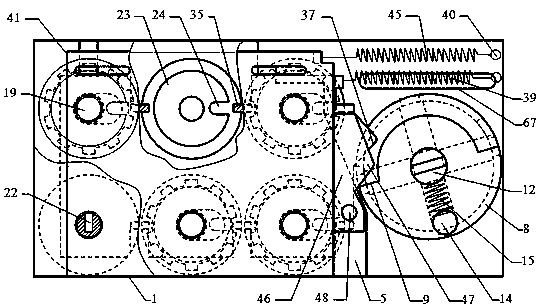
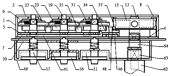
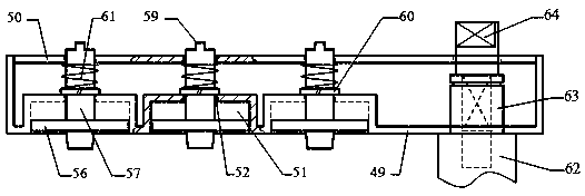
[0063] Such as figure 1 , 2 As shown, the hole-sealing type mechanical combination lock includes a lock body 1, a lock outer panel 49 and a handle 62, and the inner side of the lock outer panel 49 is assembled with a back plate 50, as shown in FIG. image 3 As shown, the back plate 50 is provided with 1 large through hole and 6 small through holes, and the outer side of the lockset outer panel 49 is provided with 6 inwardly recessed cylindrical knob shallow holes 51 and 1 handle mounting hole, each An alignment star (not shown in the figure) is provided directly above the shallow holes of the knobs, and a central through hole 52 is provided in the center of each shallow knob hole 51, which is coaxial with the six small through holes of the back plate 50 respectively. The handle mounting hole is coaxial with the large through hole on the back plate 50 . Six mutually independent knob disks 56, knob shafts 57 and knob springs 61 are movably assembled in the lockset outer panel...

Embodiment approach 2

[0086] The difference from Embodiment 1 lies in that the shape of the swing rod is different, and the connection mode when the swing rod drives the lock bolt to move is different.

[0087] Such as Figure 38 As shown, there is no oblong hole at the end of the fork A72. Such as Figure 40 ,41 , 42, the lock body 1 is provided with a lock bolt driving plate 69, and is located at the upper part of the inner side of the turntable cavity 6, and its right end is provided with a push-pull opening 70, and is movably assembled with the end of the fork A72, and the push-pull opening 70 The left side is provided with slide pin 71, and this slide pin 71 is perpendicular to lockbolt driving plate 69, and both are fixedly assembled by riveting or welding, and slide pin 71 stretches out to the outside of lock body 1 after being movably inserted into unlocking slideway 67, slide pin 71. A spacer is assembled on the protruding part, and its end is provided with an annular groove to assemble ...


PUM


Abstract

The invention discloses a closed-type mechanical code lock and relates to the field of dial-type combination mechanical code locks. The six dials of the code lock are correspondingly arranged on separate dial shafts; the unlocking codes of the dials can be replaced; the operation is simple, accurate and reliable; when insertion plates in a lock body are inserted into all openings of the dials at the same time, the lock can only be opened; and the lock body is internally provided with a sealing plate. During combination, a knob shaft in the outer panel of the lock can pass through the corresponding through hole of the sealing plate to complete the number checking operation, but the dials and the insertion plates have no contact; when the lock is opened, the sealing plate first closes a checking channel for checking numbers and re-drives to unlock, that is, when the dials make contact with the insertion plates, the checking channel is closed, so the position of the dial opening cannot bejudged at all, that is, the technical opening cannot be performed; when a handle is strongly reversed, the handle can be idling with overload protection; even if the outer panel of the lock is removed or destroyed, the lock cannot be technically opened; and the exposed camshaft can still idle.

Description

technical field [0001] The invention relates to the field of rotary disc-type number-checking mechanical combination locks, in particular to a hole-sealing type mechanical combination lock. Background technique [0002] The application range of the turntable-type mechanical combination lock is relatively wide. As a mechanical card group mechanism, it is often used on parts that need to be locked, such as file cabinets, vaults, safes, safes, security doors, and carry-on items (such as suitcases). Since then, there have been a series of problems, mainly reflected in the following aspects: [0003] One is that the unlocking process is very inconvenient. The main reason is that the registration process takes a relatively long time, so it is rarely used on civilian anti-theft doors. In particular, the combination lock with multiple turntables on the same axis needs to be rotated in both forward and reverse directions, which is very inconvenient to operate. Safes, safes, and tr...

Claims


Application Information

Patent Timeline
Patent Type & Authority Patents(China)
IPC IPC(8): E05B37/12E05B17/20E05B15/00
CPCE05B15/00E05B17/20E05B17/2084E05B37/0048E05B37/12
Inventor 吕雪寒
Owner BEIHUA UNIV
Learn More