High Boost DC Converter with Switched Capacitor

A technology of DC converters and switched capacitors, applied to output power conversion devices, conversion equipment without intermediate conversion to AC, electrical components, etc., can solve the problems of high switching voltage stress, reduced work efficiency, and unsatisfactory performance. The voltage stress is small, the ripple is reduced, and the effect of high gain is satisfied

Inactive Publication Date: 2020-08-11
TIANJIN UNIV
View PDF5 Cites 0 Cited by
  • Summary
  • Abstract
  • Description
  • Claims
  • Application Information

AI Technical Summary

Problems solved by technology

Although SL and SC converters can achieve relatively high voltage conversion gains, they are still limited and cannot meet the needs of many industries
At the same time, the switching voltage stress in the above circuit is high, which reduces the operating efficiency

Method used


Image

  • High Boost DC Converter with Switched Capacitor
  • High Boost DC Converter with Switched Capacitor

Examples


Embodiment Construction

[0014] Embodiments of the present invention will be described in further detail below in conjunction with the accompanying drawings.

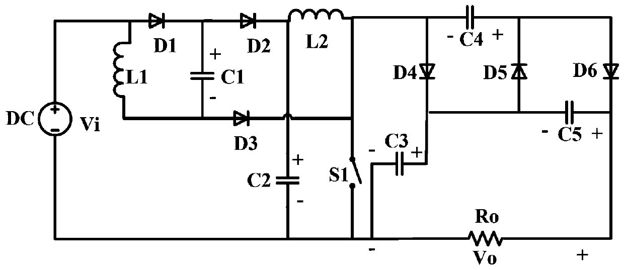
[0015] A high step-up DC converter with switched capacitors, such as figure 1 As shown, it includes input DC voltage Vi, a MOSFET switch tube, inductors L1 and L2, capacitors C1, C2, C3, C4 and C5, diodes D1, D2, D3, D4, D5 and D6, and output load Ro. The anode of the input DC voltage Vi is connected to one end of the inductor L1 and the anode of the diode D1, the cathode of the diode D1 is connected to one end of the capacitor C1 and the anode of the diode D2, and the other end of the inductor L1 is connected to the other end of the capacitor C1 and The anode of the diode D3 is connected; the cathode of the diode D2 is connected with one end of the inductor L2 and one end of the capacitor C2, the cathode of the diode D3 is connected with the other end of the inductor L2, one end of the MOSFET switch S1, the anode of the diode D4 and the capaci...


PUM


Abstract

The invention relates to a high-boost direct-current converter with a switched capacitor. The high-boost direct-current converter comprises an input direct-current voltage Vi, a MOSFET switching tubeS1, inductors L1-L2, capacitors C1-C5, diodes D1-D6 and an output load Ro; the positive electrode of the Vi is connected with the L1 and the D1, and the negative electrode of the D1 is connected withthe C1 and the D2; the other end of the L1 is connected with the C1 and the D3; the negative electrode of the D2 is connected with the L2 and the C2; the negative electrode of the D3 is connected withthe L2, S1, D4 and C4; the other end of the C4 is connected with the D5 and D6; the negative electrode of the D4 is connected with the C3, D5 and C5; the other end of the C5 is connected with the D6and the Ro to serves as the positive electrode of the output direct-current voltage Vo; and the negative electrode of the Vi is connected with the C2, S1, C3 and Ro to serve as the negative electrodeof the output direct-current voltage Vo. According to the converter, the design is reasonable, the high-voltage conversion gain is realized, the requirement for high gain in industrial application ismet, the efficiency of the direct-current converter circuit is improved, ripples of the output direct-current voltage Vo are reduced, and the converter can be widely applied to the field of direct current conversion.

Description

technical field [0001] The invention belongs to the technical field of DC converters, in particular to a high-boost DC converter with switched capacitors. Background technique [0002] In recent years, with the wide application of high-voltage DC switching power supplies, step-up DC / DC converters have become more and more popular in many industrial fields. According to whether there is isolation, DC / DC converters are divided into isolated and non-isolated converters. [0003] The isolated converter is to add the AC link to the basic DC-DC converter to achieve a higher voltage conversion rate. The AC link usually uses a transformer to achieve isolation between the input and output, so the converter is also called a direct current converter. - AC-DC converter. Generally, isolated DC converters are used in the following situations: 1) The output terminal and input terminal of the DC converter need to be isolated. 2) The desired ratio of output and input voltages is much grea...

Claims


Application Information

Patent Timeline
Patent Type & Authority Patents(China)
IPC IPC(8): H02M3/07H02M1/14
CPCH02M1/14H02M3/07
Inventor 李冬辉刘玲玲姚乐乐张耀镭
Owner TIANJIN UNIV
Why Eureka
Try Eureka